Flow – Project Post 7

Project title: Flow

Team: Julia Kosier & Yiting Liu

Accomplishments

Julia:

  • Added code to integrate color sensor readings with current code
  • Debugged unstable color sensor code & rewrote sound sensor code for more visible results

Yiting:

  • Printed the 3d printing model
  • Finished sewing the sleeve and its extra part to attach the color sensor on
  • Glued the optic fibers to the skeleton of the wings
  • Worked on the stabilizing structure of the wings
  • Finished designing for the poster


images


  • material list copy your material list from last week. If you have added any new items, include them and highlight them in red. If you have removed items from last week, include them with an orange background.
Part/Material Price Quantity Link to a purchase location
1 Side Glow Fiber Optic Cable 1.5mm~8mm Optical Fiber For Lighting Decorations

[1.5mm for 15 meters]

$15.99 w/o tax 1 https://www.ebay.com/itm/Side-Glow-Fiber-Optic-Cable-1-5mm-8mm-Optical-Fiber-For-Lighting-Decorations/253189403496?ssPageName=STRK%3AMEBIDX%3AIT&var=552285229283&_trksid=p2057872.m2749.l2649
2 Color sensor $7.95 1 https://www.adafruit.com/product/1334
3 16 gauge floral wire $11.99 1 https://www.amazon.com/gp/product/B00T831TFA/ref=ppx_yo_dt_b_asin_title_o00_s00?ie=UTF8&psc=1
4 Fabrics $3.99/yd

Including shipping total is $14.18

2 yards https://www.fabricwholesaledirect.com/products/sheer-voile-fire-retardant-fabric?gclid=Cj0KCQiAk-7jBRD9ARIsAEy8mh7xxCRl9hFRSNDtoD39ELNlrFHEVmJTnGmABucK8v3UQuPzZhtuZJoaAgeFEALw_wcB&fbclid=IwAR34tdd2dbImfbFrF7y8HEeAAJFUZJpFmekLj1aYBwW7GRi0Cw8Gx2MD5G4
5 Cellophane $15.99 1 https://www.amazon.com/gp/product/B07GR4NCC9/ref=ppx_yo_dt_b_asin_title_o01_s00?ie=UTF8&psc=1
6 Heat spray $5.77 1 https://www.amazon.com/gp/product/B000PCWRMC/ref=ppx_yo_dt_b_asin_title_o02_s00?ie=UTF8&psc=1
7 Elastic $.60/foot 10 feet https://www.strapworks.com/Elastic_p/e.htm
8
9


  • areas of concern now you have gotten started on your project, write a paragraph to articulate the areas in which you are most concerned about for your project.  Highlight areas where you are looking from help.

Areas of concern:

  • We need better support system for the wings to make it stabilized [Maybe we could also use more elastic strap to stabilize the wings]
  • We also need to start working on the back circuit design right away

Project Post #7

Project Title 

Heart Rater

Project  Team

Sungjin (SJ) Park

One sentence that describes your project 

  • Winter glove that reads and indicates your heart rate zone on winter activities.

Weekly Accomplishments

  • Covered inner wires with gray yarn that matches the color of the glove
  • Battery and wires are fully connected to the glove.

Image

Material List 

  • Part/Material: Lithium Ion Polymer Battery
  • Price: $6.95
  • Quantity: 1
  • Link to a purchase location: https://www.adafruit.com/product/2750


  • Part/Material: Adafruit Circuit Playground Express
  • Price: Provided in class
  • Quantity: 1


  • Pulse Sensor (Heart-Rate Monitor)
  • Price: $24.99
  • Quantity: 1
  • Link to a purchase location:  https://shop.openbci.com/products/pulse-sensor?utm_medium=cpc&utm_source=googlepla&variant=22543672899&gclid=Cj0KCQjwjpjkBRDRARIsAKv-0O12qE-56tiH7XDqo-T9Cz1l4Yf1ybwdN9RlAyg_Nkxs_yUG0b9LqbsaAkcxEALw_wcB


Areas of Concern

  • Wires on back layer should be covered the following week. Soldering needs to be firm enough to not break again.

InGlove – Post #7

Curt, Shruthi, Vedant

Project Sentence

Home Automation

Smart glove that helps the user control their TV and smart switches/lights using hand gestures

Taltos-oid (SRF)

Human augmentation device providing users with an extra thumb for everyday tasks.

Weekly Accomplishments

Curt –

[Note for showcase: I will need power for my laptop / backup for SRF power supply]

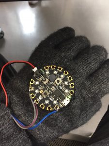
First major accomplishment this last week was putting in the time to construct the flex sensors for the glove. My current status with this task is that all of the flex sensors are constructed, tested, and sewn onto the glove.

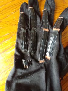
Pinky and ring finger lower flex sensors are completely sewn and have been tested with my Analog Discovery for a valid flex signal.

I then moved onto sewing the conductive thread to connect the flex sensors to wires that will lead to the microcontroller. After several approaches / experiments I found a relatively simple solution to interface between wires (with female headers) and the conductive fabric. My current status is the first one has been sewn on and tested. I plan on completing the rest of these this week by end of day Wednesday.

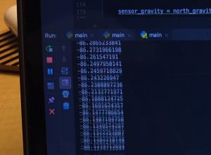
On a seperate thread of work I have worked on the firmware for the SRF. Currently I am debugging the firmware as I continue physical development efforts. Additionally, I have experimented with the Adaboost random forest approach to determine joint states. I need to write a program that runs on my laptop that communicates to the firmware level that I have written. To that end, I did define and implement a JSON interface in the firmware.

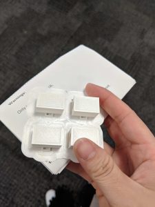
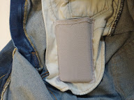
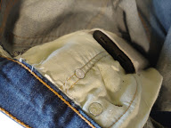
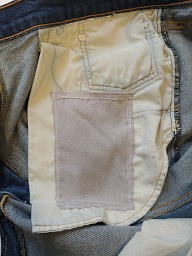
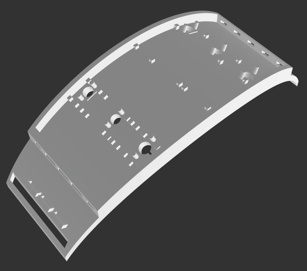
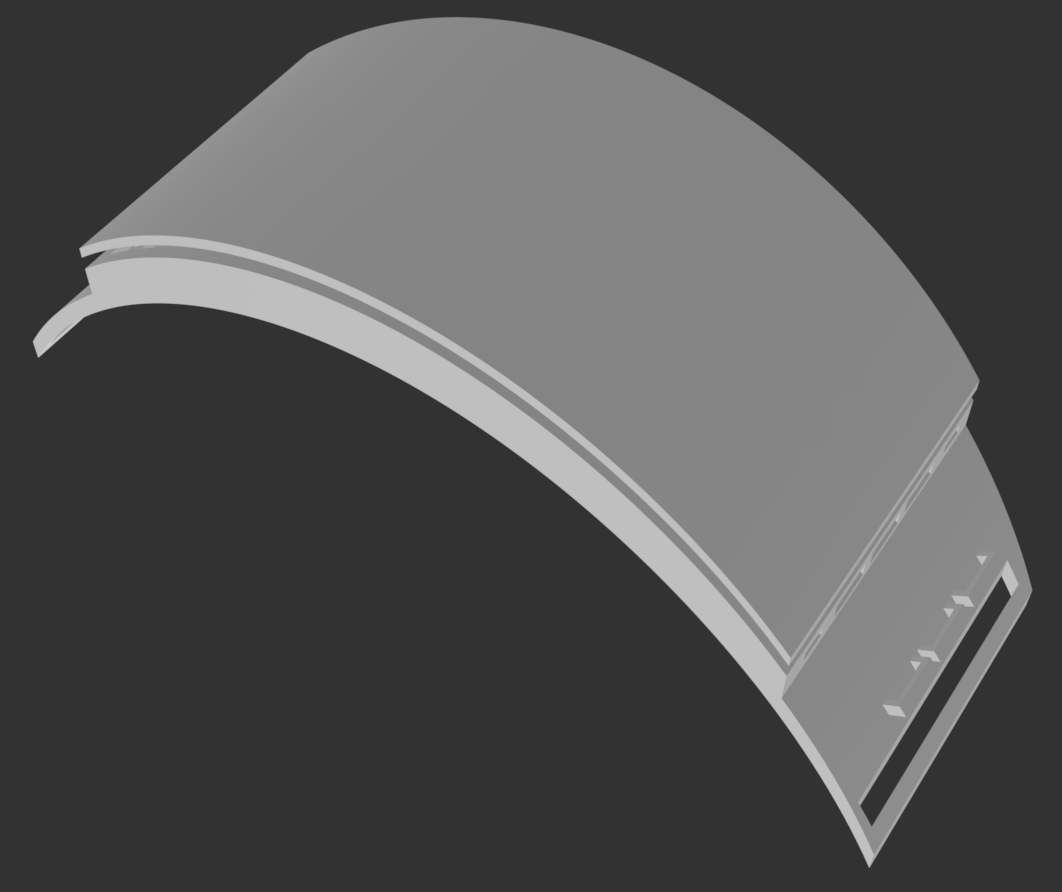
Finally, on Thursday last week I received my final shipment of parts which included the fourth servo needed to rework the finger. After reworking the design several times (as documented in the pictures below) I came up with a solution that works mechanically.

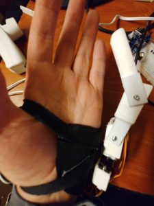
Added rotation joint at bottom. Finger collides with hand when rotating. Also the finger movement is restricted as it sits in a uncomfortable  spot in space around hand.

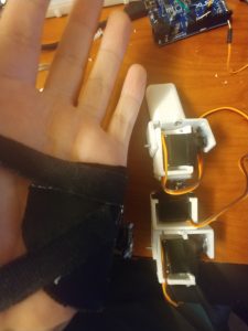
Rotation joint in middle, this allows better movement in 3D space but rotation joint is too close to hand causing collision with the protrusions from the finger.

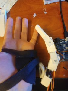
Changing the angle that the finger sits at to prevent rotation collisions and make it feel more natural in the space around the hand. Problem is this is a larger finger / extends from hand further.

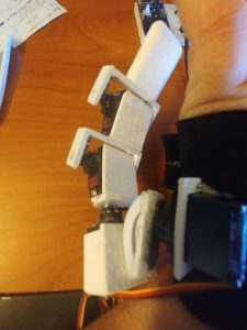
Also the piece I built is out of broken 3D printed hinges, copious hot glue, and part of a command hook taken from my wall. Looks fine several feet away but not as aesthetically pleasing close up.

There are several issues with this final version of the robotic finger. Namely, the grip torque is further reduced, size/bulk increased, and abundance of hot glue. While I acknowledge these issues as failures of the current design, it should nonetheless inform future iterations.

Remaining Tasks

  • Construct wire to conductive thread adapters (4x)
  • Sew on conductive thread adapters
  • Debug / verify correct operation of flex sensor circuit
  • Build microcontroller wrist-strap with velcro
  • Build microcontroller board using solder protoboard
  • Debug / verify correct operation of firmware for both finger and glove
  • Write PC program for controlling finger joint states from flex data. Requires collecting and training ML data
  • [Optionally] Get either Bluetooth serial or WiFi websocket for wireless operation
  • Poster design and language complete

Shruthi –

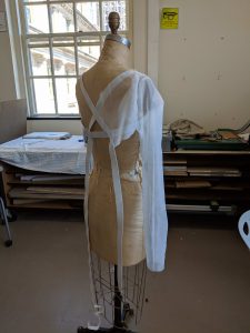
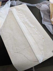
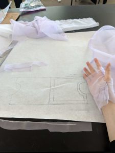
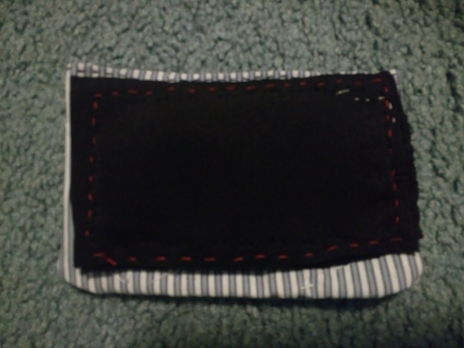
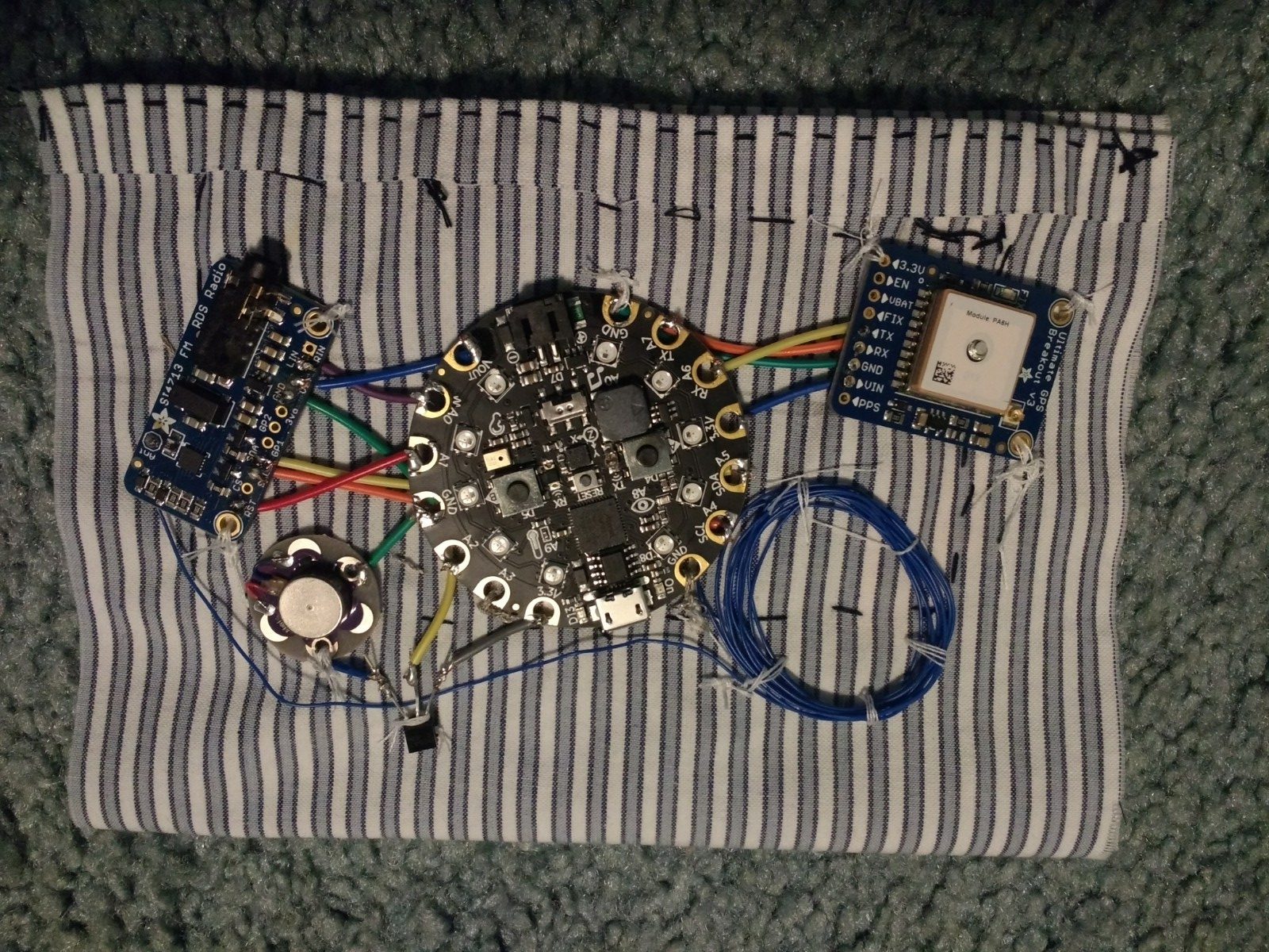
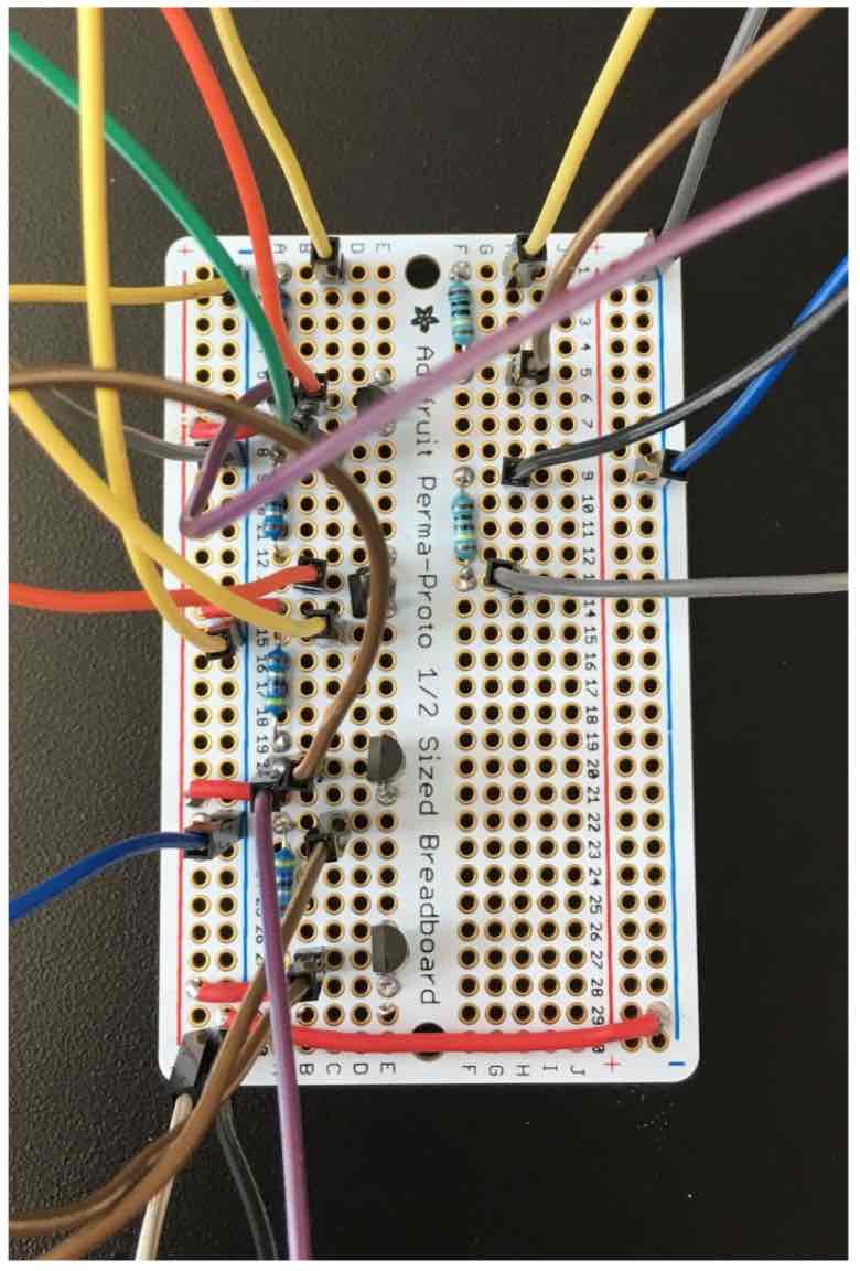
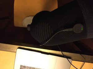
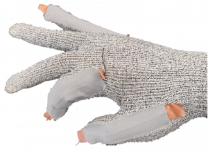
This week we spent time on discussing and developing ideas for the poster and its contents. I made an initial draft and working towards improving it. We also made a few more fabric flex sensors and sewed them on. Also planned the layout of where the circuitry goes into. The idea is to have no cross overs or short circuits. Another challenge we seem to run into is to try and figure out the best way to power the particle photon. We could use a power bank, however we aren’t sure how it has bearings on the overall user experience and the portability factor. We may also consider sewing on a Li-Po battery to Vin of the photon. We also had a  discussion with Kevin on how to best demo the functionality. I am looking at pulling the browser data from particle website either using a browser emulator or java-script and working towards building a local server to do this. Here is a photograph of the sewed on flex sensors.

Vedant –

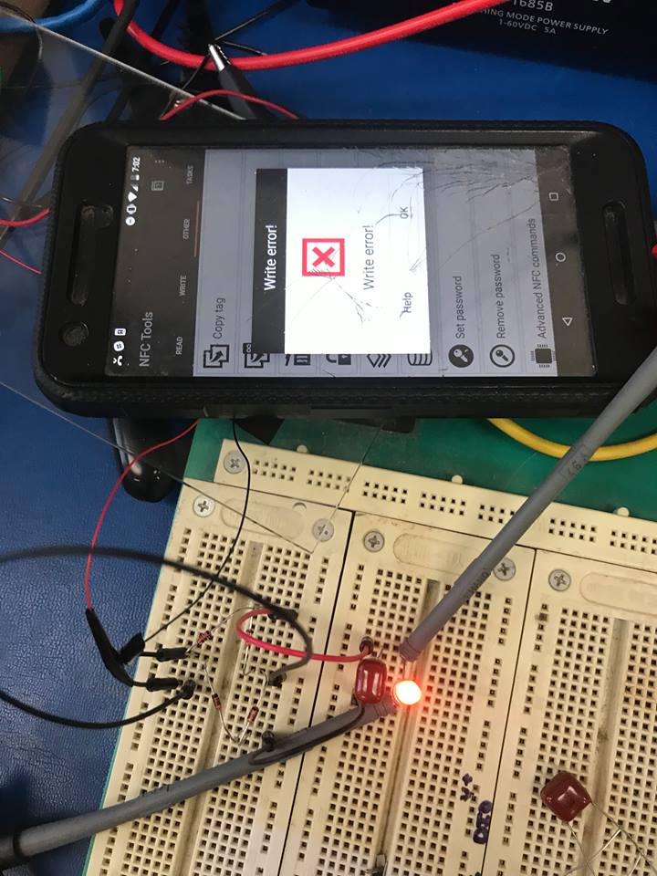
This week we worked on sewing the fabric DIY sensors onto the glove, the poster, and well as finalizing the code for the IR transmitter. I was able to understand how to convert the IR Hex Codes I had to Raw Codes, which is then used in a pulse and delay combo in a for loop that loops over the Raw IR codes list. I was able to get the IR connected to the photon to emit IR signals turn on/off my TV and increase volume.

Material List

Home Assistant Sub-Project

  1. Particle Photon – $19.00 (1)
  2. Flex sensor – 4.5 inches – $12.95 (1)
  3. Flex sensor – 2.5 inches – $7.95 (1)
  4. IR LEDs

*We decided to go ahead with more of the DIY flex sensors. So we might possibly need more velostat and copper sheets and conducting thread.

SRF Sub-Project

Already purchased / owned

  1. Glove for prototype [final version subject to change based on prototype]
  2. Sparkfun IMU – $14.95 (1)
  3. Flex Sensor – 4.5 inches  – $15.95 (1)
  4. ESP32 Dev Board – $15.00 (1)
  5. High Torque Micro Servo – $9.95 (3)
  6. Resistive Force Sensor – $7.00 (1)
  7. Flex sensor – 4.5 inches – $12.95 (1)
  8. 3D printed  SRF – ~$14.00 (N/A)
  9. Glove [Final design] – $14.99 (1 ordered)
  10. PCBs – N/A (N/A ordered)
  11. High Torque Micro Servo – $9.95 (1)
  12. 3.3V to 5.0V Level Shifter IC – ~$1.00 ( 1)
  13. I2C Servo Driver Board [in case issue with microcontroller persists] – $14.95 (1)

Need to Purchase / Being Shipped

  1. Resistive Force Sensor – $7.00 (5)
  2. Flex sensor – 4.5 inches – $12.95 (3) and/or Flex Sensor 2.5 inches – $7.95 (8)

Areas of Concern

Curt –

Primary concern for this week is finishing the sewing of conductive thread on the glove, wiring the microcontroller with all components, and writing/debugging the software for the project. There is plenty of work to do and not much time.

Secondary concern is the poster which I will probably have time to work on Tuesday evening / night. Again not much time to complete these items.

Shruthi –

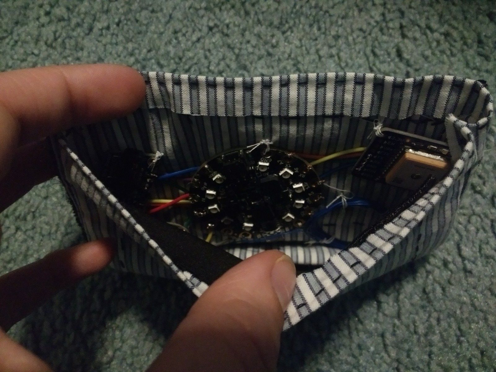
A few areas of concern at this stage is to how to best integrate the circuit and battery into the fabric keeping in mind its aesthetic and portability requirements

Vedant  – 

Areas of concern as of now include getting the code for the flex sensor integrated with the IR emitter and making sure we are able to sew the circuit onto the glove in time.

project post #7

project title: Qi Jeans

project team: Greggory Van Dycke

weekly accomplishments:  This week I made sure my project was totally complete and worked on my project poster for the fashion show.

images:

.

material list:

areas of concern: I do not have any concerns that this time about my project.

Project Post #7: ROETE

Project Post #7: ROETE

Radio Outdoor Emergency Transmitter Electronic

Natalie Tack

One sentence that describes my project: A device that transmits location via radio when activated by the user in an emergency.

Weekly Accomplishments:

I soldered all of the electronic components together, including the circuit playground express. I then hand-sewed (my sewing machine was broken) my little pocket together and sewed the components to the pocket. I also sewed the button to the front of the pocket and connected the conductive thread to the gnd and A3 pins on the circuit playground express.

Images:

Material List:

  1. FM Stereo Radio Transmitter
    1. Price: $20
    2. Quantity: 1
    3. Link: https://www.amazon.com/Adafruit-Stereo-Transmitter-RBDS-Breakout/dp/B00SK8ME4Y#
  2. GPS Module
    1. Price: $40
    2. Quantity: 1
    3. Link: https://www.adafruit.com/product/746
  3. Vibration Module
    1. Price: $6.95
    2. Quantity: 1
    3. Link: https://www.sparkfun.com/products/11008?_ga=2.218497438.624035456.1554576553-2048369341.1554576553
  4. Patch
    1. Price: $20
    2. Quantity: 1
    3. Link: http://eliteembroideryandscreenprinting.com/
  5. Transistor
    1. Price: $0.30
    2. Quantity: 1
    3. https://www.digikey.com/product-detail/en/on-semiconductor/PN2222ABU/PN2222AFS-ND/6534&?gclid=EAIaIQobChMIn9Kmo5G84QIV1LjACh2IEQZDEAQYAyABEgJoIfD_BwE

Areas of Concern:

I do not have any concerns for this past week. My primary focus for this next week will be getting the little pocket and patch installed onto the jacket. The pocket being inside the jacket’s front chest pocket and the patch being sewed onto the front outside the jacket’s front chest pocket.

Project Post #7

PROJECT POST #7

Project Title: Vis Hat  

Project Team: Lydia, Fu, Jay


Weekly Accomplishments:

Lydia:

  • Found example/reference code for data visualization
  • Researched and learned more programming language syntax for d3.js visualization software (Javascript, HTML, CSS)
  • Researched setting up live data visualization
  • Planned and designed wiring setup for final prototype
  • 3d modeled final prototype for headset with integrated wiring setup
  • Attempted 3d printed final prototype in elastic material (design construction not compatible with elastic or flexible material)
  • 3d printed backup model in PLA hard plastic (will still work better than first prototype because of more specific measurements and wire structuring)

Fu:

  • Design and finalize circuit setup.
  • Soldering circuit on proto board and check its functionality.
  • Setting prototype and test it.

Jay:

  • Wrote code for emitter cycles
  • Looking into D3 data visualization
  • Poster design and some of the text

Images:

  • (Image 1) The following image shows the design and position on how emitters, resistors, transistors, and photodiodes are positioned.
  • (Image 2) The image below shows the actual circuit built on proto board, which looks less bulky than using breadboard. Also, we reduced some redundant pins and integrated them together. This circuit is our final version.  
  • (Image 3 & 4) These images are of the updated prototype model with added specified dimensions, wire structuring, and cover.


Material List:

title/link # needed price/unit notes shipping and tax TOTAL PRICE:
arduino due 1 34.43 34.43
NPN transistor 1 5.99 this one unit contains ~200 resistors 5.99
730nm emitter 2 8.61 9.54 26.76
850nm emitter 2 1.46 2.92
850 max nir detector/sensor 2 5.37 9.02 19.76
bluetooth 1 28.95 RN41XVC (with chip antenna) 8.81 37.76
850nm emitter 2 1.46 To account for trial and error hardware testing 7.99 9.45
9 volt battery power supply adapter 1 5.99 5.99
3d print in elastic material 1 0 0

Project Concerns:

This week with the new prototype printed and all the hardware reconfigured in smaller more condensed setup, we are ready to construct the final complete Viz Hat. Here are some concerns for the week:

  • Obtaining data that’ll work. We need to do several tests this week to make sure the data we’re gathering can be used consistently for the visualization.
  • Getting the visualization ready. We’ve found some already existing code we’d like to implement with the parameters of our data, but we need to work on initializing it in live time and getting the data to transfer from the Arduino serial port to D3.js’s software.

Other than these two concerns, the remaining steps we need to take should be pretty straightforward. These include finishing the headset assembly, which is all planned out and configuring the demo. Our plan for the demo is to (1) have the Viz Hat set up on the head manakin, (2) display and explain the concept and process with our poster, (3) have a laptop/screen with a looping video of the Viz Hat working (gathering data and producing a visualization in the background). This 3rd component alleviates the potential for any technological difficulties that could arise with a live demo.

Project Post 6: Lit Lehenga

Individual: Jessica Fernandes

Weekly accomplishments:

  • I acquired all my materials and continued to test the functionality of my code
  • Materials I have: Circuit Playground Express, light sensors,LEDs, Enclosure, power source

One Sentence:

  • Lit Lehenga is a traditional Indian garment that illuminates in darkness to mimic the magic of Diwali and celebrate Indian culture.
I purchased 40 white leds
I also got an enclosure for the circuit in case I want to incorporate it into the design, but it might be too bulky to be worn

Linked below are my pictures of:

Materials

Areas of concern

  • Ensure that the additional LED sequins are triggered by the light sensor; it doesn’t function as planned currently. Connect the hardware in a wearable configuration to plan where they’ll ultimately be sewn.

Project Post #6: Wearable Circuits

Wearable Circuits

John Compas

One – Line Description

Exploring the possibilities of wearable circuitry with and without power sources

Accomplishments

I’ve got NFC power to work with a couple of NFC tags I bought.

They’re easy to integrate into the circuits I’ve built already. I just remove the IC at the feed point of the antenna and attach 30 gauge wires to the feed points. Above, I’ve got a simple full bridge rectifier working although the LEDs light up just as well without one. The rectifier can output about 3 volts DC at 10mA, which isn’t a lot of power, but enough to work with. I’m also going to try to put two of them in parallel to see if I can increase the power output.

The nice thing about the NFC tags is that they are readable from my phone, and many other android phones, so I won’t need a dedicated reader or writer. However, my phone isn’t very powerful and the distance the LED or other circuitry remains power is only a centimeter or two.

I’m going to try to utilize my own NFC antennas, as these frequencies are so low this system is more working like a transformer. Thus, as long as I reasonably match the number of loops of the commercial antennas, this should work decently well. The above design is for 5 leds powered by one tag.

Coming Week

I’ve got a lot to do. I’m going to focus first on getting simple LED circuits to work with these NFC tags and maybe with batteries. I’m mostly thinking of aesthetic wristbands or armbands that have an array of LEDs that wrap around your arm.

I’ve also found that the MOSFETs I bought can seemingly be operated like little “capacitive touch” buttons, although I think they’re actually functioning differently. If I connect the ground of the circuit to the wearer, they can actually turn off the MOFSETs by touching their gates. I’m going to explore using this to turn on and off the LEDs on the wearer and try to get the MOSFETs to hold this state somehow. Ideally, I’d like a pattern to show up on a wearer when they approach an NFC reader.

Materials List:

  1. Clear Covering Self-Adhesive 
    1. https://www.amazon.com/Magic-Cover-Adhesive-Contact-Projects/dp/B000BPF9QY/ref=sr_1_26?crid=QOW16D2H82TC&keywords=vinyl+adhesive+paper&qid=1551742619&s=gateway&sprefix=vinyl+ad%2Caps%2C195&sr=8-26
    2. Count: 1
    3. Cost: $5.50
  2. Silhouette Temporary Tattoo Paper
    1. https://www.amazon.com/Silhouette-MEDIA-TATTOO-Temporary-Tattoo-Paper/dp/B0043WJ3OA
    2. Count: 1
    3. Cost:  $8.99
  3. Spray Adhesive
    1. https://www.amazon.com/3M-General-Purpose-45-Adhesive/dp/B000PCWRMC
    2. Count: 1
    3. Cost: $5.77
  4. Speedball Gold Leaf
    1. https://www.amazon.com/Bememo-Imitation-Gilding-Crafting-Decoration/dp/B0722X91YR
    2. Count: 1
    3. Cost: $6.99
  5. SPMWH22286D5WAP0S2 (Samsung LEDs)
    1. Count: 100
  6. RC1210JR-07100RL (100 Ohm Resistor)
    1. Count: 100
  7. SL3S1203FTB0,115 (UHF RFID)
    1. Count: 10
  8. C1812C102KGRACAUTO (Capacitor)
    1. Count: 10
  9. NTR5105PT1G (Diode)
    1. Count: 10
  10.  Conductive Guitar Tape
  11.  NSR201MXT5G (RF Schottky Diode)
  12.  ST25DV16K-IER6T3 (NFC IC)
  13. RF700072 (NFC Antenna)
  14. RF700070 (NFC Antenna)


Project Post #6: Scavenger Stuffs

Weekly Accomplishments:

This week was tackling the major issue of communicating between the RFID scanner and the Unity game. Thankfully, a solution has finally been found. It feels a bit over-complicated, but it works under manual testing and should hold up all the way:

  1. Power up Pi and RFID Read/Writer
  2. Power up computer on the same network, ssh to pi
  3. Scan pendant against RFID reader, output to file
  4. Rsync file to the computer via ssh (hopefully this will be automated in the near future)
  5. Run the dummy unity program which looks at that location and updates gamesparks accordingly
  6. Pull results from gamesparks in-game

The setup for this took a while, but it ends up being fairly simple in the pi and application. The video below shows the file transfer occurring.

Also done this week, more component acquisition. We have the paint and clay needed to finish up the goat, and two additional pis and scanners have been ordered, along with 10 extra tags. I will need 2 additional microSD cards, but they have not been ordered.

As for plush progress, I have a good idea of what the third animal will be and have some fabric set aside. The anteater plush now has eyes as well.

For the game side, login/registration was fixed, and the app was finally hooked up to read in acquired animals from the server. Users can tap to swap which anima they use in-game.

Images:

Video this week, showing off the new RSync between our pi and my laptop

https://drive.google.com/open?id=1uwSZU0IbvlXcYmhjvJBxuMjCMQBm7wx7

Additional Material List:

    1. Battery/USB Charger (still torn on which I’ll be using, but right now it isn’t a priority)
    2. MicroSD Card (this might add a bit to the expense of the plush
    3. Cost of Plastic for 3D printing the pendants (depends on whether I’m crushing the old pendant ot make the new one, or working around the original key fob. Again, I’ll make this call once I have a base product working).

Areas of Concern:

Right now, biggest concern is with soldering the RFID Reader/Writer and making sure it works consistently. Right now, every component works individually, but linking them up is always cause for concern. Here’s what it looks like now:

RFID to File: Tested, but torn apart for transport. Code is good, hardware needs to be redone

File to Computer: Tested as of 4/14

Dummy Unity to Game: Tested as of 4/7

Essentially, we have 3 groupings of technologies that need to be tied together. This means we need, respectively:

  1. The RFID reader/writer to work consistently after soldering
  2. A scheduled task to run RSync
  3. The dummy file to be updated to grab the file from the new location

3 is a quick fix, but requires me to take a few notes before implementing. 2 can be skipped until everything else is done because the test can be run manually. 1 is what concerns me most, since my soldering skills are pretty stale. We’ll see how it goes.

Project Post #6

Safe Sleeve

Jake Cordover

One sentence: Safe sleeve is a functional knee sleeve that conveys knee data that has historically been confined to either clinical settings or prohibitively expensive motion capture equipment.

Weekly accomplishments: This past week I focused on trying to smooth out the flexion and extension data. It has improved to a much more consistent level that seems to better reflect the rough angle, however I think there is still room for improvement. One area in particular that I’m interested in looking into is using Euler angles rather than the quaternion approach I’m using now. While Euler angles may have some limitations and are not as robust as quaternions, this may be ok in my use case. Nonetheless I am planning on implementing this approach so I can compare the two approaches.

Images:

Below is the brace on a knee with sensors attached.

Below is the data readout of the brace on a knee flexed around 90 degrees.

Materials:

Materials (no change):

Part/Material Price ($) Quantity Link
Potential IMU 1 117 with discount secured 1 https://yostlabs.com/product/bluetooth-mini/
Knee Sleeve 1 16.97 1 https://www.amazon.com/PowerLix-Compression-Knee-Sleeve-Basketball/dp/B01MQYADOT/ref=sr_1_5?keywords=powerlix+knee+sleeve&qid=1552264456&s=gateway&sr=8-5
Knee Sleeve 2 20 1 https://www.amazon.com/Zensah-Knee-Compression-Sleeve/dp/B00GPU7QRO/ref=sr_1_6?keywords=zensah+knee+sleeve&qid=1552264496&s=gateway&sr=8-6#customerReviews
3D printing and associated costs TBD TBD TBD


Areas of concern: Getting the data as accurate as possible is my main goal as well as concern right now. Hopefully using Euler angles proves provide better data. If I can achieve this, I’d like to focus on creating my custom enclosure so the sensors don’t have to be screwed down at all times.