Final Project
Author: Curt Henrichs
I propose to make a supernumerary robotic finger (SRF) with position detection glove. This will consist of a robotic thumb mounted near the pinky, mirroring the biological thumbs location and movement. This thumb will be constructed with 3D printed mounting brackets and high torque micro servos. The thumb will be mounted to a modified wrist guard as used in skateboarding in order to distribute the weight of the thumb onto the wrist. The wrist guard must not impede normal hand function. Finally, there will be a series of flex sensors mounted onto a glove to detect the joint state of the wearer’s fingers. This along with an inertial measurement unit will report the hand pose information to an algorithm to control the SRF. For this project the algorithm will be constrained to a simple hard-coded heuristic approach, but future work will use data driven AI to learn the wearer’s intent off their hand position.
Target Audience
I am primarily developing this project for my own curiously. Specifically, I would like to wear the device for a full day to record hand position data, record failures and inconveniences, record interactions with others and their perception, and explore contexts of applicability. This in turn allows me to further develop a machine learning algorithm, iterative design improvements, HCI insight, and further general SRF usage taxonomy respectively.
As for the eventual end-user, this technology could potentially augment any life task however I am mostly interested in applying the technology to the manufacturing and construction spaces where the ability to do self-handovers is an important aspect of the task. An example would be screwing an object overhead while on a ladder. The constraints are that a person should keep three points of contact while holding both the object and the screwdriver. If they need to do all three, they may lean the abdomen onto the ladder which is less effective than a grasp. Instead with several robotic fingers (or a robotic limb) the object and screw driver could be effectively held/manipulated while grasping the ladder. Another example the should relate to this class is soldering where the part(s), soldering iron, and solder need to be secured. This could be overcome with an SRF thumb to feed the solder to the tip of the soldering iron while holding the parts down with one’s other hand.
My Motivation
Academically I am motivated by the research opportunities in the space. There are many unanswered questions as this technology has not been popularized yet. Though my interest stems from the philosophy that I adhere to, that being humans are not the end state of evolution. I am excited to construct technology that not only affects my physical appearance but my physical capacities.
Inspiration and Novel Proposal
As far as I am aware in the SRF literature I am providing a modest incremental improvement. Wu & Asada worked with flex sensors however they were only interested in the first three fingers and did not attempt to model the hand position directly [1,5]. Arivanto, Setiawan, & Arifin focused on developing a lower cost version of Wu & Asada’s work [2]. One of Leigh’s & Maes’ work is with a Myo EMG sensor which is not included in the project [3]. They also present work with modular robotic fingers though they never explore the communication between finger and human in that piece [4]. Finally, Meraz, Sobajima, Aoyama, et al. focus on body schema where they remap a wearer’s existing thumb to the robotic thumb [6].
My project will take inspiration from Wu & Asada (along with other work in flex sensors as to detect finger movement), Meraz, Sobajima, Aoyama, et al. will provide inspiration of using a thumb as the digit being added, and Leigh’s & Maes’ work in modular fingers will be the inspiration for how I construct the wrist connection. The novelty is bringing these pieces together to form a wearable that I can run a long-term usability test with myself as the subject.

Figure 1: Supernumerary robotic fingers found in literature.
Design
Figure 2 displays my thoughts on how the glove will be laid out. My first experiment will be whether one flex sensor is sufficient to capture the joint position for a finger. The position of the IMU is mounted on the glove instead of the wrist in order to capture more accurate absolute orientation of the fingers. Figure 3 shows the mounting location of the finger along with sketches of the robotic finger itself. This is inspired off of Wu & Asada’s work though I am going to building one with micro-servos instead of standard scale. These sketches are subject to change as I construct the glove.
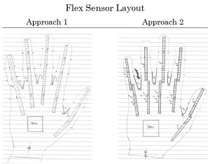
Figure 2: Glove sketch with alternate approaches.

Figure 3: Robotic finger sketch (top) fusion 3D image, (bottom) top and bottom view of finger mounting position.
Materials
- Electronics
- ESP32 – Microcontroller w/ Bluetooth and Wi-Fi
- Flex sensors
- Micro servo motors
- Resistive pressure sensor
- Vibration motor
- IMU
- Clothing
- Glove (Light weight, breathable)
- Snowboarding / skateboarding arm brace
My Skills
- Have experience in:
- Soldering
- Circuit design
- Programming
- Need to master:
- Sewing / other soft materials knowledge and skills
- Project management
- 3D printing
Timeline
- Milestone 0 – Initial Prototype (February 24)
- Glove w/ several flex sensors.
- Determine either approach 1 or 2
- Detect both span between fingers and flex of a finger
- Power supply not a concern
- Milestone 1 – Technology shown to work (March 16)
- Glove w/ flex sensors
- Position of hand captured, data transmitted to PC for processing / visualization
- IMU captures absolute orientation, data transmitted to PC for processing / visualization
- Power supply and integration started
- (If time) Robotic finger 3D printed
- Milestone 2 – Technology works in wearable configuration (April 6)
- Full integration
- Glove w/ all flex sensors, IMU mounted
- Wrist-brace w/ finger mounting, processor mounting
- Power supply complete
- (If time) Robotic finger controlled
- Milestone 3 – Technology and final wearable fully integrated (April 20)
Potential Challenges
First major challenge that I have accounted for is that one flex sensor may not be enough to determine the joint state of a finger. Thus, as I will outline later, my first experiment is to see if this is the case. The next is that I do not have time to develop all components. This would be the worst case but if it does happen, I believe that I will prioritize the sensor glove before the fingers. While I have to learn more about 3D printing, I am also not a novice so given access and time I should be able to print out several parts for a robotic finger. Finally, the algorithm to convert from pose to finger position will most likely be a simple heuristic based on gesture. This could mean inadvertent triggering of a movement even if this was not the intent. While a failure of the algorithm, I am least concerned with this aspect for the term.
First Step
I have already purchased (though as of writing this still in shipping) the parts I need for my first hardware experiment. I need to figure out whether I can determine which of three finger joints is bending using one 4.5” flex sensor. If this is successful, then I will use 5 of these to capture pose information. Otherwise I will need to purchase 10 2” flex sensors to detect the finger position in one direction. As for the spread between fingers, I plan on using 1” flex sensors but for the initial prototype 2” flex sensors will work. I also plan on using an IMU to determine absolute orientation with respect to the Earth. All of this will be mounted on a relatively thin winter glove that I have purchased.
I will need to sew on the flex sensors for the one finger and one spread sense along with some mounting for the IMU. This will be connected to an Arduino Uno clone that I have to report the data back to my PC for visualization. The most challenging portion of this prototype is developing the code to determine position followed by with visualizing the hand state.
Inspiration References
- [1] F. Y. Wu and H. H. Asada, Implicit and Intuitive Grasp Posture Control for Wearable Robotic Fingers: A Data-Driven Method Using Partial Least Squares, IEEE Transactions on Robotics, vol. 32, no. 1, pp. 176-186, Feb. 2016.
doi: 10.1109/TRO.2015.2506731
- [2] M. Ariyanto, R. Ismail, J. D. Setiawan and Z. Arifin, Development of low cost supernumerary robotic fingers as an assistive device, 2017 4th International Conference on Electrical Engineering, Computer Science and Informatics (EECSI), Yogyakarta, 2017, pp. 1-6. doi: 10.1109/EECSI.2017.8239172
- [3] Sang-won Leigh and Pattie Maes. 2016. Body Integrated Programmable Joints Interface. In Proceedings of the 2016 CHI Conference on Human Factors in Computing Systems (CHI ’16). ACM, New York, NY, USA, 6053-6057. DOI: 10.1145/2858036.2858538
- [4] S. Leigh, H. Agrawal and P. Maes, Robotic Symbionts: Interweaving Human and Machine Actions, IEEE Pervasive Computing, vol. 17, no. 2, pp. 34-43, Apr.-Jun. 2018. doi: 10.1109/MPRV.2018.022511241
- [5] F. Y. Wu and H. H. Asada, “Hold-and-manipulate” with a single hand being assisted by wearable extra fingers, 2015 IEEE International Conference on Robotics and Automation (ICRA), Seattle, WA, 2015, pp. 6205-6212. doi: 10.1109/ICRA.2015.7140070
- [6] Segura Meraz, N., Sobajima, M., Aoyama, T. et al. Modification of body schema by use of extra robotic thumb, Robomech J (2018) 5: 3. doi: 10.1186/s40648-018-0100-3
