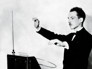
The concept of Theremin Jacket comes from the Theremin, an electronic musical instrument that could be controlled without physical contact by the performer. Thus, the Theremin Jacket we want to make allows the wearer to control an external connected MIDI to play music without any physical contact.
2) Who is our project for?
Theremin Jacket is for people who are fans of music, or more specifically, fans of the electronic musical instrument Theremin. It could also provide a chance to those without any experience of playing musical instrument to play music.
3) Describe how someone would use the developed device. What are the steps that a user would go through to interface with the technology?
First, there will be a switch on the jacket that allows wearers to turn on/off the circuit. When circuit is on, sensors on the jacket will read positions of wearers’ hands and arms in real time. After that, those data will be transmitted to the external connected MIDI through bluetooth and the MIDI will receive and play corresponding tones.
Besides the features mentioned above, we might also want to allow wearers to play different type of sounds by moving different parts of body instead of just two arms (ex. Playing drum by moving one foot up and down). We could also try allowing user store customize MIDI instrumental sounds in an external device and display sounds by speaker or earphone.
4) What makes your project different from existing products?
As we have researched so far, we have not found a wearable technology that support Theremin and MIDI music that allows user to move and control the flow of music. There are products that allow user to move but produce funny music (e.g. movement jacket), and products that allow user to control music but in a fixed, not fully interact-able way (e.g. arm MIDI keyboard, MIDI shirt, etc).
Our project aims to provide an easy to control interface to detect user hand movement. User adjust pitch by putting hands in different heights ( or different relative position from the other device ) and control music flow by the touch of buttons and proximity to body.
Inspirations
12th December 1927: Professor Leon Theremin demonstrating his theremin. The theremin was the world’s first electronic musical instrument. It is played without actually touching any part of the instrument. Film scores of the 40s and 50s used the instrument to eerie effect and it makes a famous appearance in the chorus of the Beach Boys hit ‘Good Vibrations’. (Photo by Topical Press Agency/Getty Images)
Sketch
Material/Tools Needed
Base Jacket
Accelerometers / Infrared Sensors / Sonars (for position detecting)
Arduino Board
Thread
Machine Needles
Battery
Skills/Concept to Master
Coding in Arduino
Connecting with MIDI
Making sensors work
Mounting sensors
Data transmit through Bluetooth
Timeline
Milestone 1 (March 25)
Try out different types of position detectors
Determine which type of position detectors to finally use
Milestone 2 (April 8)
Get the base jacket
Mount sensors on the jacket
Data transmit through Bluetooth
Connect with MIDI
Improve overall precision
Milestone 3 (April 22)
Improve overall precision
Aesthetic adjustments
Fallback Plan
We are planning to implement a jacket that allows wearers to control different parameters of music (i.e. pitch, amplitude or duration). If later in this semester we could determine that we have fallen behind what we have expected, we could: 1) Instead of having both arms to work, just implement and make sure one arm to work, and decrease the number of parameters of music we are going to control, or 2) Instead of making a Theremin Jacket, just simply make a position detector for parts of a body.
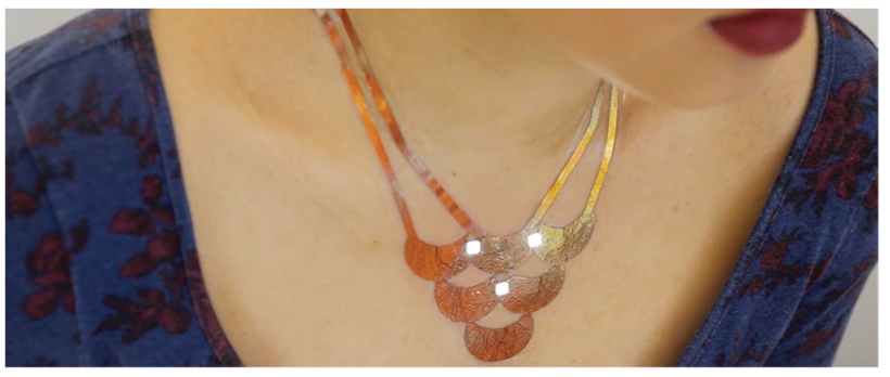
I would like to explore the possibilities of using gold leaf, tattoo paper, and SMT components to create wearable circuits. These temporary tattoos could be artistic, lighting up in response to the wearer’s environment, or more utilitarian, such as utilizing near RFID to respond to a request with sensor data and an ID. I’m interested in investigating the space of what is possible with this topology especially with antennas and RFID technology.
My project is for anyone, to show to demonstrate the capabilities of the technology and fascinate people.
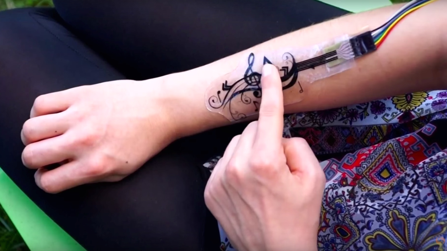
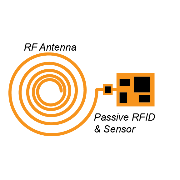
Interfacing with a complete device would be simple. The tattoo would be applied like any other with a spray bottle of water to get the adhesive to activate on the wearer’s skin. In the case a passive UHF RFID tag, the sensor would lay dormant until activated by a strong RF emitter. Storing the received RF energy in a capacitor, the integrated sensor IC would read a sensor value and respond to the request as dictated by UHF protocol ISO 18000-6C. The reader would then report this value to a tablet or phone.
More artistic designs could change LED color and intensity based on skin temperature and conductivity, or by the intensity of received RF signals in a certain band. For example, LEDs could visualize the intensity of different frequency signals around the wearer using multiple antennas with varying resonant frequencies.
Existing work as focused more on either ease of use, or improving some technical aspect of this technology. I would like to focus on antennas and poetic interaction with the user.
Project Inspiration
Duo-Skin, MIT
A project from a group of MIT, Duo-Skin aimed to demonstrate the ease of creating wearable, temporary tattoos. They were successful in creating computer-powered MIDI controllers, RFID tags, and letting a team of volunteers quickly create their own circuitry.
iSkin, Carnegie Mellon
iSkin was a much more engineered approach and came before the MIT study. They demonstrated interfaces using layers of cPDMS (a silicone elastomer) and touch. The study is good source of detailed information about how their capacitive touch sensors work but was less “friendly” than the Duo-Skin.
Project Sketch
Example UHF RFID Sensor, passively powered that responds with ID and data.
(I’m not great at antenna design, the feedpoint should probably be in the middle, but this is the idea)
Materials & Tools
Gold leaf
Tattoo paper
SMT capacitors, transistors, LEDs, and ICs
Altium Designer
Small lithium-ion coin cell batteries
Impedance analyzer
Oscilloscope
DC power supply
Solder paste or solder
Solder gun, heat gun, and reflow oven
Laser cutter (potential)
Electric stencil cutter
Skills & Concepts
I will need to research antenna design thoroughly, as I have little experience with it in the past. I’m aware of the challenges with circuitry and antennas in the gigahertz range but have never designed any myself.
Cutting the stencils will (hopefully) not be done by hand, but the layering of the tattoos will need to be done by me. Soldering the SMT components to the gold leaf will also potentially be a challenge. Burning the leaf out might be easy, but it seems like a challenge that has been overcome in the past so I’m hopeful that I will find a method.
Timeline
March 8: Order Prototype Materials, Find Tools & Initial Design
Generate a more detailed list of materials needed for an initial prototype and find suppliers online
Order materials and components
Layout initial circuit designs in EasyEDA, layout footprints in Altium and generate stencil cut-outs
March 13: Demo of Circuitry
Utilize gold leaf on cardboard or another surface to create initial powered circuitry
Attempt to transfer to body, and develop a procedure for insulating layers
March 25: Duplication
Successfully duplicate previous work, with battery-powered sensors, capacitive touch buttons, and LEDs
Attempt to create RFID responsive tags with a simple IC and antenna
Analyze antenna properties, characteristic impedance, and model gold leaf in antenna design software such as EMWORKS
April 8: Improvement
Start work on passively powered RFID tags & sensor
Iterate on the circuit construction process
If work is progressing well, attempt a powered Bluetooth LE circuit
April 22: Environmental Testing
Demonstrate design in the real world, and test durability and usability
Make small changes based on the user experience of wearers
Prepare multiple samples and demonstration “tattoos” for the show in April.
Fallback
As a whole, I see the antenna aspects of this project as the most challenging. I have a decent amount of experience in conventional circuit design and microcontroller programming. The circuits here are not particularly challenging, outside of the feed point with the antenna.
The gold leaf could present a challenge, but DuoSkin reported it as relatively durable with sufficient trace widths. If it isn’t working for some reason, other conductive tape or material could be attempted.
As a bare minimum, I expect to at least duplicate the results gathered by MIT in their DuoSkin study. Part of the aim of that paper was the technical ease at which circuits like these could be created, so I don’t anticipate duplication taking longer than the two months that we have.
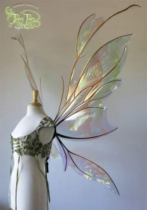
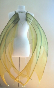
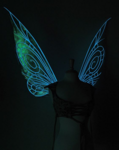
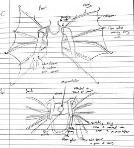
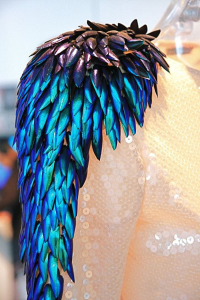
We are going to create a set of light-up wings controlled by both a sound sensor and a color sensor. The light, emitted by RGB LEDs through side emitting fiber optics, will change colors based on input from a color sensor on an attached sleeve, while it will also blink in time with the beat of music received by the sound sensor.
We envision our project as a way for performers and artists to express themselves – particularly, our project would pair well with a dance performance. It could also be of interest to cosplayers.
The technology should be simple for the user. We envision a simple harness to support the wings along with a sleeve. The user would power the wings on via a switch and put them on with the harness. The sound sensor would work automatically – all the user needs to do is put on music. The color sensor would then be contained in the sleeve and, as the user places the sensor near objects, the color of the lights will change.
There are other existing products that flash lights to the beat of music; however, the incorporation of the color sensor as well makes ours unique. Additionally, our artistic vision is different by aiming for a fairy-like, fantasy-driven look.
We derived inspiration from a number of existing projects:
Additionally, there are existing products that are similar to our idea:
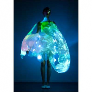
(a dress with responsive lights)
(“wings” with lights integrated intended for use in performance)
Here is our planned design:
Materials/tools we’ll need:
18 gauge floral wire
Side emitting fiber optics
Color sensor
Circuit Playground Express
RGB LED lights
Plastic tube to connect the led and the optical fiber
Cellophane
Soft switch made in class
Elastic (for straps)
Sheer fabric for sleeve
Skills we’ll need to master:
Sewing
Connecting LEDs to fiber optics
Construction of wings (attaching floral wire)
Timeline:
February 27th: Purchase samples of materials
March 10th: Coding should be finished
March 25th: All technology should be working
March 28th: Wing construction should be about 50% finished
April 8th: Wings should be wearable
April 15th: Technology should be integrated with wings
April 22nd: Project should be fully functional
Our fallback plan is to decrease the scope of the wings and create something more like a sleeve, like these projects:
So long as we have an aesthetically pleasing project with lighting responsive to sound and color detection, we will consider the project a success.
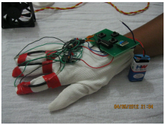
Our project is composed of three subprojects: the hand gesture / position glove and two applications for said glove.
For the first part of the final class project, we would like to make smart gloves that helps the user send remote signals using hand gestures as commands. While there are many similar kinds of gloves that exist as projects, a lot of those gloves do not make use of the wide variety of sensors available in the market. Additionally, some of the projects seemed to be made inefficiently in that they seemed to be pretty bulky for how much they can do. We want to explore how those existing gloves could be improved in not just functionality but also aesthetics. Thus, we would work on this project not as an invention, but rather a demonstration/experiment
1.1 FUNCTIONALITY:
The functionality of the glove would include things such as pressure, motion and flex sensors to capture various gestures, and associate these gesture-controlled commands to control the application sub-projects as detailed below. Communication will be handled with Bluetooth or WiFi depending on the application being implemented.
1.2 USAGE:
The typical process to use the glove will start with a user placing the glove onto their hand and performing calibration. While the details of calibration will need to be worked through as we develop the software, it will most likely take the form of the user positioning their hand into a predefined pose. Depending on the end application, we could either provide the user with a list of predefined guidelines that maps gestures to tasks or allow customization of the said mapping. In the latter case, we would have to perform experiments on the kinds of gestures that are best read and provide the user with a set of guidelines on how to make customization most efficient.
We now proceed to describe separately the idea and plan for Curt’s supernumerary robotic finger as well as Vedant and Shruthi’s Wearable home automation.
2. SUPERNUMERARY ROBOTIC FINGER
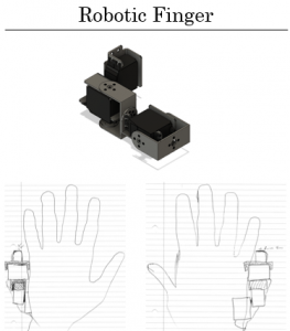
Using the glove developed as hand position input, Curt will construct a supernumerary robotic finger mounted next to the left hand pinky finger. This digit will mirror the biological thumbs location and joint structure. The robotic finger will map the hand gesture to user intention which in turn maps to a joint configuration for the finger. By the end of the term a simple hard-coded heuristic function will be developed to perform this mapping.
Curt is primarily developing this project for his own curiously. Specifically, Curt would like to wear the device for a full day to record hand position data, record failures and inconveniences, record interactions with others and their perception, and explore contexts of applicability. This in turn allows Curt to further develop a machine learning algorithm, iterative design improvements, HCI insight, and further general SRF usage taxonomy respectively.
As for the eventual end-user, this technology could potentially augment any life task however I am mostly interested in applying the technology to the manufacturing and construction spaces where the ability to do self-handovers is an important aspect of the task. An example would be screwing an object overhead while on a ladder. The constraints are that a person should keep three points of contact while holding both the object and the screwdriver. If they need to do all three, they may lean the abdomen onto the ladder which is less effective than a grasp. Instead with several robotic fingers (or a robotic limb) the object and screw driver could be effectively held/manipulated while grasping the ladder. Another example the should relate to this class is soldering where the part(s), soldering iron, and solder need to be secured. This could be overcome with an SRF thumb to feed the solder to the tip of the soldering iron while holding the parts down with one’s other hand.
In the SRF literature Curt is proposing to provide a modest incremental improvement. Wu & Asada worked with flex sensors however they were only interested in the first three fingers and did not attempt to model the hand position directly. Arivanto, Setiawan, & Arifin focused on developing a lower cost version of Wu & Asada’s work. One of Leigh’s & Maes’ work is with a Myo EMG sensor which is not included in the project. They also present work with modular robotic fingers though they never explore the communication between finger and human in that piece. Finally, Meraz, Sobajima, Aoyama, et al. focus on body schema where they remap a wearer’s existing thumb to the robotic thumb.
2.1 WEARABLE HOME AUTOMATION:
While these gloves could have many different functions, we would like to focus on using these gloves as part of a smart home, including functions like controlling the TV, smart lights, as well as a Google Home/Alexa (through a speaker). This could especially be useful for people with disabilities (scenarios where voice based communication is not easy), or even just a lazy person.
This project utilizes ideas of Computational gesture recognition to create a wearable device. We use components of sensor systems and micro controllers in conjunction with a mobile application, (preferably android) along with fundamentals of circuit design. Our project management technique would involve a mix of waterfall and iterative models, keeping in mind the timeline available so as to create a viable solution to home automation.
The idea is to have the glove communicate to an android application either via bluetooth or a wifi module, and the phone in turn can control several other devices. Since applications like the Google assistants have powerful AI technology integrated into them, can we extend those capabilities from a beyond the phone on to a wearable fabric?
Also, it brings in the concept of a portable google home of sorts. This means that we do not need to install a google home in every room. This project is meant to be pragmatic and the consumer is the general population. It could also be of extra help to people with disabilities.
3.INSPIRATION
SRF takes inspiration from Wu & Asada (along with other work in flex sensors as to detect finger movement), Meraz, Sobajima, Aoyama, et al. will provide inspiration of using a thumb as the digit being added, and Leigh’s & Maes’ work in modular fingers will be the inspiration for how Curt constructs the wrist connection. The novelty is bringing these pieces together to form a wearable that one can run a long-term usability test.
https://ieeexplore.ieee.org/document/6629884
http://maestroglove.com/
SRF:
[1] F. Y. Wu and H. H. Asada
[2] M. Ariyanto, R. Ismail, J. D. Setiawan and Z. Arifin
[3] Sang-won Leigh and Pattie Maes
[4] S. Leigh, H. Agrawal and P. Maes
[5] F. Y. Wu and H. H. Asada
[6] Segura Meraz, N., Sobajima, M., Aoyama, T. et al.
We find significant work done in the general area of gesture recognition using a glove. However, those gesture interpretations have been applied in different domains. We did find a project or two where gloves where used for home automation. However, the choice of sensors is different from what we plan to use. (flex and pressure).
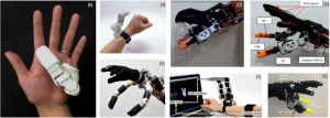
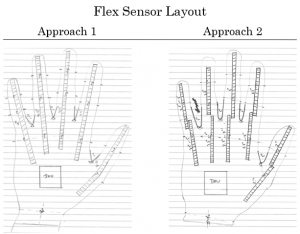
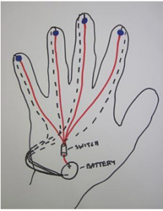
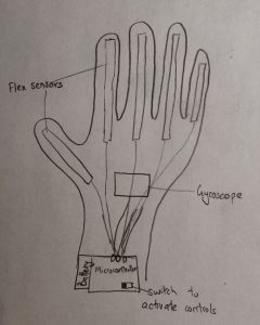
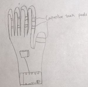
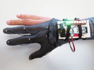
The following sketches were developed for the project pitch and compiled here due to their similarity. The important aspects to note with the glove is the presence of flex sensors used to capture finger movement, touch sensors on the fingertips, and an inertial measurement unit to capture hand orientation.
Glove:
SRF:
5. MATERIALS
Electronics:
Microcontroller (w/ Bluetooth and WiFi ex. ESP32, Adafruit Flora, Particle Photon, Arduino, Possibly external Bluetooth or WiFi Module)
Flex sensors
Resistive pressure/force sensors
Vibration motor
IMU (Gyroscope, accelerometer)
Micro servos (For SRF)
Infrared LED emitter / receiver
Clothing / Physical Materials:
Glove
Wrist brace (For SRF)
3D printed components (case, mounting)
6.SKILLSET LIST:
Curt:
I come into this project with experience soldering, designing circuits, and programming. My talent is mainly in embedded system programing with C. I will need to master sewing and other soft materials skills and knowledge to hack a glove in an aesthetically pleasing fashion. Another skill hurdle will be 3D printing as I have some familiarity during undergrad where I worked with a 3D printer as a hobbyist but never formally trained. Finally, I will need to further hone my project management skills due to the ambitious scope as laid out.
Vedant:
While I have some experience with programming, this project would require a lot of microcontroller programming, so that would be the main thing I would have to master. The project would also require some knowledge of IoT so I would be looking more into that as well.
Additionally, I have experience using tools in the makerspace (3d printing, laser cutting), so if I have time to focus on the aesthetics, I could use those skills to help me improve the looks. However, it is a given that I will also have to learn soldering well to compact the design, as well as sewing to make the glove look nice.
Shruthi:
I have prior experience with arduino programming. I have a decent understanding of C and Python programming. Also, I can contribute in integrating the sensory data to a mobile application. I am more comfortable debugging on an IDE and not so much directly on a hardware device and I need to improve my skillset in this direction.I could also help with the aestheic aspect of the glove in sewing and stitching. However, I do not have significant experience in these areas.
7.TIMELINE
7.1 MILESTONE 1
Technology shown to work (March 25)
Glove
Glove w/ all flex sensors
Position of hand captured, data transmitted to PC/phone for processing / visualization
IMU captures absolute orientation, data transmitted to PC/phone for processing / visualization
Power supply and integration started
SRF
Robotic finger 3D printed
Assistant
Test whether the bluetooth or wifi module would work best to connect to the Google Assistant
Look into Google assistant API and see what functions/commands can be given using a third part app
7.2 MILESTONE 2
Technology works in wearable configuration (April 8)
Note after this point, project focus splits from being glove focused to application focused. Curt will take on SRF subproject and Shruthi & Vedant will take on the home assistant subproject.
Glove
Refinement of aesthetics
Power supply and integration complete
SRF
Robotic finger controlled
Brace developed
Assistant
Basic functioning app developed
Required IR codes and assistant commands obtained
7.3 MILESTONE 3
Technology and final wearable fully integrated (April 22)
Glove
Error reduction, final iteration on design
SRF
If time allows a one person “user study” to capture longer term data
Else refinement of the finger control / design
Assistant
Fully functioning app that receives commands from gloves and sends commands to Google Assistant app to control smart home
Aesthetic gloves that house the electronics, battery and sensors ergonomically
8. FALLBACK PLAN
Glove:
We will be starting with an experiment with one finger to see if one flex sensor is sufficient to capture the gesture information necessary. The answer found may show that one flex sensor is sufficient for the assistant subproject but not the SRF project. Alternatively it could be that flex sensors themselves are not sufficient. To that end, this experiment will be done early in order to integrate the findings into our design.
The minimum that we will consider success is a glove that can output preprogrammed gesture commands that are loosely coupled to the state of the fingers. For example curling the index finger will be a command.
SRF:
Curt will have to learn more about 3D printing to develop the SRF physical components. Additionally, a mounting system needs to be developed. Depending on how time consuming this step is, Curt may need to develop a simple, proof of concept, heuristic for the final demonstration. This could result in non-ideal finger movement that does not track the intent of the wearer, however failure of the algorithm in some cases will be deemed acceptable as this is still an open research area.
Assistant:
We will also integrate the sensor signal data and manage to establish communication to a phone via either bluetooth or wifi. We would probably begin by controlling a smart light or a single device and eventually try to build larger integration with the Google home app. We would first develop a prototype, a rather simple proof of concept and try to get a single instance of end to end communication channel functional. However, since this is still in experimental stages, we cannot guarantee the accuracy and reliability of its function.
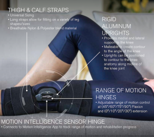
The goal of SafeSleeve is to create a soft, functional knee sleeve that interfaces with a mobile device, reading back live data about knee motion, including flexion, extension, and hopefully excessive lateral translation. This type of device could benefit numerous individuals including, but not limited to: healthy athletes, rehabbing athletes, and rehabbing patients. Data about knee motions are readily available in a clinical setting, however most patients and athletes do not spend the majority of their recovery or activity in a clinical setting— by providing access to this data anywhere, patients can complete range of motion exercises within bounds set by their recovery team, coaches can assess positioning or form on movements, improving performance or enhancing safety, and motion extrema can be flagged, allowing for earlier injury detection. Additionally, providing a mechanism of injury could potentially lead to more accurate diagnoses.
To use SafeSleeve, a user would first put on the sleeve and turn it on with a switch or button. Depending on design implementation, the sleeve will require either consistent and precise positioning on the knee, or it will require a short calibration period. After the device has been positioned or calibrated, the user will open a companion application to select the mode of usage: either continuous live feedback, or sport mode. Live feedback would continuously display current knee metrics on a mobile device, while sport mode would keep all data on the sleeve, flag any data extrema, and transfer the data to a device at a later time. Finally, the data on the companion application can be analyzed in a number of ways like max extension/flexion/lateral translation, whether a set motion boundary was breached, and potentially how many reps of flexion/extension were performed in non-sport mode. The ability to track motion data over longer lengths of time may also be useful.
Similar Products
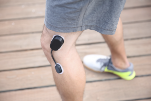
After perusing over similar, existing products, it was concluded that there is no other readily available functional knee sleeve that tracks positioning. However, two somewhat similar products were found, one of which was the Donjoy X4. This product differs in that it is a hard knee brace meant for post-operative knee arthroplasty. Hence, this product would not be suitable for athletes looking to track during activity— not to mention price. One of the benefits of the design of this project is if the planned design can be executed, sleeves can potentially fit under a number of braces, combining the benefits of the bracing stability, compression, and data. The other somewhat similar product is the Smart Knee, which is essentially two sensors connected by a bend sensor that attaches directly to the skin with adhesive pads. One, like the Donjoy, two sensors attached directly to the skin would not be optimal for athletes wanting a functional solution, and two the product does not appear to be sold to directly to consumers, and the cost for developer kits start at $2500. See below for images of the Donjoy X4 and the Smart Knee.
The smart knee is pictured above.
DonJoy X4 pictured above.
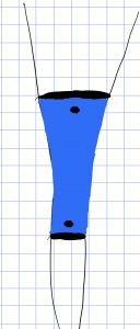
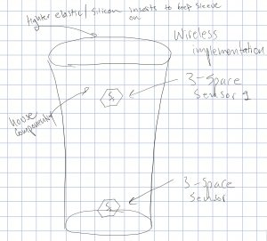
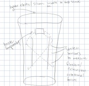
Sketches of Sleeve
Implementation and Materials
At this point, there are two potential implementations to make this product a reality. The first implementation involves using IMUs (inertial measurement units) or other wireless sensors. These sensors would be utilized with mathematics in order to provide the desired data. The benefits of going this route would nullify the necessity of precise and consistent sleeve placement. The disadvantages of going this route includes price, reliability and accuracy of sensors, and fairly sophisticated mathematical prerequisite knowledge required to achieve the data. For simplicity, this will be called the wireless implementation.
The other implementation involves utilizing a material that changes resistance, such as a flex senor, stretch sensor, stretchy conductive fabric, or conductive thread, and mapping the data to a known set of values to achieve the knee data. The benefits of this implementation include less involved knowledge of mathematics and a less expensive approach. However, there is concern about the durability of such materials holding up in strenuous activity and achieving and maintaining the exact fit of the sleeve from which the mapped values were accrued. Additionally, while maybe not a concern for this project, any future sleeves produced will need to be calibrated with a goniometer to each particular user. This implementation will be called the wired implementation.
The following materials will be required regardless of implementation:
If mini Bluetooth sensors not used,(37.50) 3-Space Nano Evaluation kitand Bluetooth module with batteries and wiring
Either excess material to make a pocket for sensors or 3D printing to make housing for electronics to be sewn down to sleeve
The following materials would be necessary for the wired implementation:
Small microcontroller like ($8.95) Trinket M0
Batteries
Either stretch conductive fabric/flex sensors/stretch sensors/conductive thread
Either excess material to make a pocket or 3D printing to make housing for electronics to be sewn down to sleeve
Skills to be mastered
Mathematical knowledge for wireless implementation
Neat, elegant sewing
3D printing to house electronics
If mini Bluetooth sensors not used, electrical/physical componentry and component communication protocols like I2C
Measuring knee angles with goniometer for calibration/comparison
Timeline
By March 11th: decide implementation plan and order materials needed
By March 18th: have all materials on hand (pending shipping) and be able to collect some type of data on mobile device
By March 25th: demonstrate that sensors provide a means of accurate knee data
By April 1st: complete final design plan and produce 3d componentry if that route used
By April 8th: demonstrate that sensor suite, perhaps temporarily integrated, produces accurate knee data
By April 15th: push to complete integration and mobile app
By April 22nd: Debug, finish app, demonstrate integrated knee sleeve works
Fallback Plan
If it is deemed too difficult to gather accurate, consistent knee data, strategic placement of soft switches on the knee sleeve could provide tactile feedback (vibration) if undesirable knee positions are realized.
Bare Minimal Outcome
The bare minimum for this project is to create a functional knee sleeve that provides some sort of feedback (data or tactile feedback) to a user. For how big of a field medical technology is, there are surprisingly few solutions to provide feedback on knee movement outside of a clinical setting. Thus, the inspiration of this project, and what will determine the success of the project is creating a functional knee sleeve, granting insights into knee metrics that are traditionally restricted to a clinical setting.
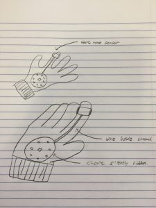
My project idea is to make wearable glove that measures heart rate.
Who is your project for?
My target potential wearers are people with high blood pressures and athletes so they can check their heart rate at any time. Mainly, 20s to 60s will be the potential wearers for my project.
Describe how someone would use the developed device. What are the steps that a user would go through to interface with the technology?
They have to turn on the switch on their device and connect to their smartphones with Bluetooth. As soon as Bluetooth is connected to their phone, wearers’ heart rate automatically starts to be recorded seamlessly. The display will be simple and direct. Only heart rate will be showed at this point of the project. A few more functions might be added in further.
What makes your project different from existing products?
The sensor itself has its pure functionality of measuring heartbeat. I am going to distinguish my project from existing features by attaching it to the glove and hiding the device underneath double layered threads. It is going to be subtle but smooth in terms of design.
Inspiration images/artists/designers/projects that are relevant to your idea
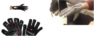
I had design inspiration from https://www.instructables.com/id/DIY-Glove-Controller-With-E-Textile-Sensors/ which has totally different feature from my idea in terms of functionality, but has aesthetic design. The glove from the link above was designed to control VR by putting input sensors on the finger tip parts. The design is what I liked the most while I was researching similar glove projects. It was made from spandex fibers to make hand and finger movements more naturally. I think I am going to implement spandex material on the first layer and wool material on the second layer so that the second layer can cover bulky parts of the device and connectors.
digital or scanned sketches of your project
My first layer of the glove.
Final look with the second layer
A bulleted list of the materials/tools you’ll use/need
ARDUINO UNO REV3
PROTOCENTRAL PULSE OXIMETER & HEART RATE SENSOR BASED ON MAX30100
Seeksmile Adult Lycra Spandex Gloves from Amazon
Bruceriver Men’s Pure Wool Knitted Gloves with Thinsulate Lining and Elastic Rib Cuff from Amazon
List of skills/concepts that you will need to master for completion
Need more experience with sewing.
A timeline
Milestone 1 (March 25): Prototype design is completed, and its function is tested by checking errors.
Milestone 2 (April 8): Attaching first layer to the second layer.
Milestone 3 (April 22): Checking for whether it is comfortably wearable and fully functional. Evaluating design in terms of aesthetics.
A fallback plan
I could use backup plan when my initial project is not going well. I will keep the idea of making tech glove and use same Arduinos but for controlling volumes or brightness on the phone by gestures. I could minimize loss by keeping similar forms and devices.
I consider my bare minimal outcome to be its functionality. If it can keep track of my heart rate on the display without falling off of my hand, it would be a success for me.
Get Worn once, Photographed once, then placed into a storage bin!
2) Who is your project for? (1-2 sentences)
My Mom, she would think it is very cool. No foreseeable commercial viability in making these dresses. At the very best, an experiment in form and materials
3) Describe how someone would use the developed device. What are the steps that a user would go through to interface with the technology? (at least a paragraph)
Put it on, be careful not to spill wine on it.
4) What makes your project different from existing products? (2-4 sentences)
Novel use of fabric manipulation– I see it as an exploration in form not yet seen in dress making. This technique and potential textile I have not seen in any other garments.
a bulleted list of the materials/tools you’ll use/need
First Vintage– 100% Polyester Crepe, Spray Starch
Second Vintage– Silk Non-woven Fabrics, Laser Cutter, Silk Cocoons
list of skills/concepts that you will need to master for completion (for example soldiering, sewing, etc)
Setting Pleats
Patience
a timeline (where you would like to be when in the project)
Here are major milestone dates for you to work around
Milestone 1 (March 25): Finished 1st Vintage of Polyester Dress
Milestone 2 (April 8): Finished Samples in Silk Non-Woven Fabrics
Milestone 3 (April 22): Finished Non Woven Silk Circle Gown
a fallback plan
what can you do to recover your project if it doesn’t go as planned?
Not applicable, because this is a dedicated experiment even a failure is a success
what is the bare minimal outcome that you would consider a success?
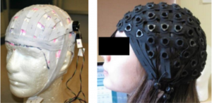
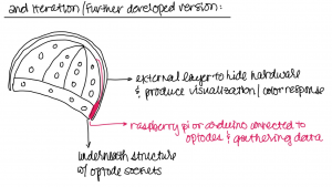
This project acts as a means to monitor brain response of an individual to environmental change, whether that be sound, light, temperature, people, etc. It will use an fNIRS technology which involves infrared sensors to monitor changes in the blood surrounding the brain close to the skull.
2) Who is your project for? (1-2 sentences)
The project will be for or adults (vs. kids or those with significantly smaller heads), ideally with hair, for short periods of time (~1-2 hrs max) as opposed to long term medical-grade studies where individuals are monitored for weeks to months at a time.
3) Describe how someone would use the developed device. What are the steps that a user would go through to interface with the technology? (at least a paragraph)
Short Term:
Color response of hat exterior to show change in data. For this we will draw from already existing color/emotion correlation research. Steps would include 1) positioning hat and optodes, 2) connecting processing device (i.e. computer, phone) using bluetooth with device, 3) observing response (hat color change, logged data)
Long Term:
Use for memory documentation. The hat could be used to track emotional response over time using optode sensors as well as coded machine learning processes to learn the specific responses of individuals. This could combine with additional sensors (light, sound, color, weather) and track the date/time, any music playing to log data spanning years. This kind of data could further be manipulated in a VR immersive space for people to expose themselves to surroundings similar to previous experiences. Such experiences could be useful for those with memory loss, in old age, in general for remembering, or for sharing experiences with new generations, family, or for historical study.
4) What makes your project different from existing products? (2-4 sentences)
Developed for personal use instead of medical use/research. Meant to be worn and integrated more seamlessly into someone’s lifestyle. Providing an experience not as visibly or experientially hindered by ‘technology.’ For personal data analysis. Not necessarily up to par with medical standards.
For completion (for example soldiering, sewing, etc)
Current Experience:
Lydia: 3d modeling, sewing, 3d printing, laser cutting, art and design, some data analysis and visualization, knowledge of current research surrounding emotion/color/sound
Fu: Mechanical Engineering, 3D modeling(Autocad, Solidworks), 3D printing, laser cutting, hardware and software connections, circuits, programming, some signal processing.
Jay: Basic circuitry, data visualization, programming, data analysis, data noise reduction
Sharon: programming (machine learning, data structure, data analysis, AI)
Skills Needed for Project:
Sewing the cap, generating 3D models, 3D printing, building connections between the hardware and software, programming (signal processing, machine learning…), AI Data manipulation, Managing and analysing data on what that the hat has record
TIMELINE (where you would like to be when in the project)
Here are major milestone dates for you to work around
Milestone 1 (March 25): The technology for the project is shown to work
1-2 sensors reading some sort of consistent data and sending to computer through arduino or raspberry pi connection.
Milestone 2 (April 8): The technology has been shown to work in a wearable configuration
Demo setup: read consistent specific input (audio, visual, motion cue). Begun development of data visualization result/ideas/programming.
Milestone 3 (April 22): The technology and final wearable are fully integrated
Full Demo: Hardware is further developed (combined sensors) and cleaner design. Process of wearing device to data vis output in response to environmental change is cleaner.
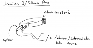
Start with one (1) optode and measure response to different environmental change (i.e. light, sound, people, temperature, etc.).
Following a set of procedures that we develop/organize (meet with current faculty and/or students about their own procedures surrounding detection of brain response to hardware development and data analysis). Coming up with our own procedures.
_________________________________________________________________FALLBACK PLAN
What can you do to recover your project if it doesn’t go as planned?
What is the bare minimal outcome that you would consider a success?
Bare Min Outcome:
Working with one optode, doing minor data analysis, and projection data visualization to show response. Not constructing a full functioning cap, but a singular sensing area that shows some response.
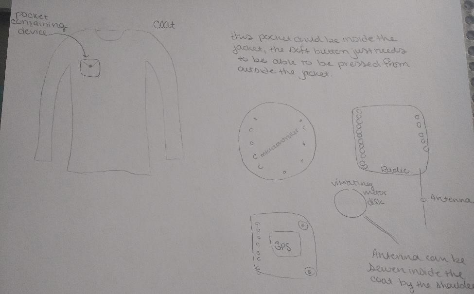
A device that transmits a prerecorded message that requests assistance at specific GPS coordinates. This happens when a user presses a button 3 times (3 times to limit the amount of accidental transmissions). The device will then respond with 2 vibrations. The device will then listen for 1 minute, if there is no more user input, the device will send the pre-recorded message. If there is user input, the transmission will be sent. The transmission will be relayed multiple times either over different frequencies or over the same frequency.
This device is for people who enjoy to spend time outdoors without necessarily carrying a phone. This device is designed to work without a phone so that if a phone breaks or is unable to send a call if an accident happens, this device can still transmit a signal over radio waves.
This product is different from existing products because most other emergency alert devices are connected to a phone or wifi. This device will be primarily for use outdoors and works exclusively with radio waves.
Something out there that is similar to what I am trying to design is an Emergency Position Indicator Radio Beacon, which is what boats use when they need help. Once someone has pushed the button, it transmits a signal on a designated radio frequency that relays the boat’s information and coordinates to the Coast Guard, it also relays all this information to an emergency contact if that is provided.
This is similar to my project, there is also a similar mechanism out there for airplanes, however, there is no designated frequency or product out there for outdoor emergencies on land in the US.
Materials:
Microcontroller (if needed, some radio transceivers have it)
GPS module
Adafruit Feather 32u4 with RFM69HCW Packet Radio – 433MHz – RadioFruit
Vibration Motor
SD card (not sure if needed, media file might be small enough)
Fabric to make soft button
Wire to connect via soldering
Skills/Concepts
More knowledge of radio transmission (radio licenses and such)
How to connect microcontroller and radio transmitter to send mp3 or wav files
A little bit of soldering (have done before)
Sewing (have done before)
A Timeline:
Before March 25: 1st: radio transmitter relays message (from file)
2nd: radio transmitter can relay message with GPS coordinates
3rd: two vibrations happen before relaying message
Before April 8: 1st: vibration happens after 3 soft button presses
2nd: after 3 button presses, two vibrations occur, one minute passes, radio transmission is sent.
Before April 22: 1st: if user presses button during one minute of listening, no message is sent
Finally: work out any last kinks
Fallback Plan: if radio signal does not transmit, will use Bluetooth to send message to emergency contacts instead
Minimal Outcome that is Success: message is sent on user input (whether that be Bluetooth, Wifi, or radio) and message does not send with user input during listening state of device.
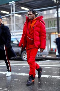
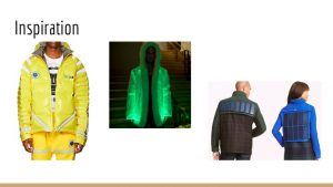
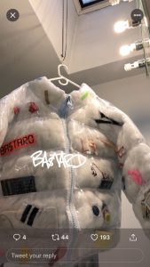
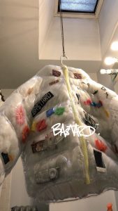
We will make a puffer jacket that lights up according to outside factors such as sound and temperature. Our project is for people who want to look good in a dark environment such as a concert or a club.
In order to use the puffer jacket, there will be an on/off switch for the lighting feature that wearers can choose as they wish. When lighting is off, wearers can wear it as a regular day-to-day jacket to keep them warm at the same time look stylish. When lighting is on, the jacket can glow or flash according to the surrounding music and/or color. The user-device interaction would be very straightforward and intuitive.
Currently, there is no LED puffer jacket on the market for purchase, which gives us a lot of room to improvise. However, there are a few lighting hoodies on the market. Most of them have either zipper lighting or fiber optic material. Since we are basing our lighting feature on a puffer jacket, there is more room for us to get creative with lighting patterns and integration of different sensors without looking too bulky.
Inspirations
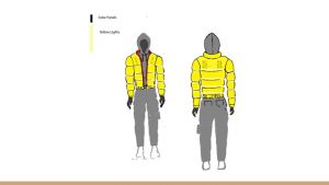
Digital Sketch
Material/Tools Needed
Ripstop nylon fabric
Batting
Thread
Battery
Machine Needles
LED lights/Fiber Optic Material
Skills/Concept to Master
Circuits + sensors
Combining tech with clothing
Timeline
Milestone 1 (March 25)
Prototype Light/Music Sensor
Order Materials
Test usage
Make a pattern for coats
Milestone 2 (April 8)
Finish sensors
Implement circuits into clothing
Milestone 3 (April 22)
Finish implementation
Aesthetic finishes
Real life testing
Fallback Plan
We are planning to implement both light and sound sensor features to the jacket. If one of the sensors do not work as desired, we can ditch the malfunction feature and implement other ones. The worst case scenario is that none of the sensors is working, in that case, we can just have LED lights that glow accordingly, but that is unlikely to happen given our current progress.