Final Project Post: Wearable Circuits

WearableCircuits

John Compas

Exploring the possibilities of wearable circuitry with and without power sources
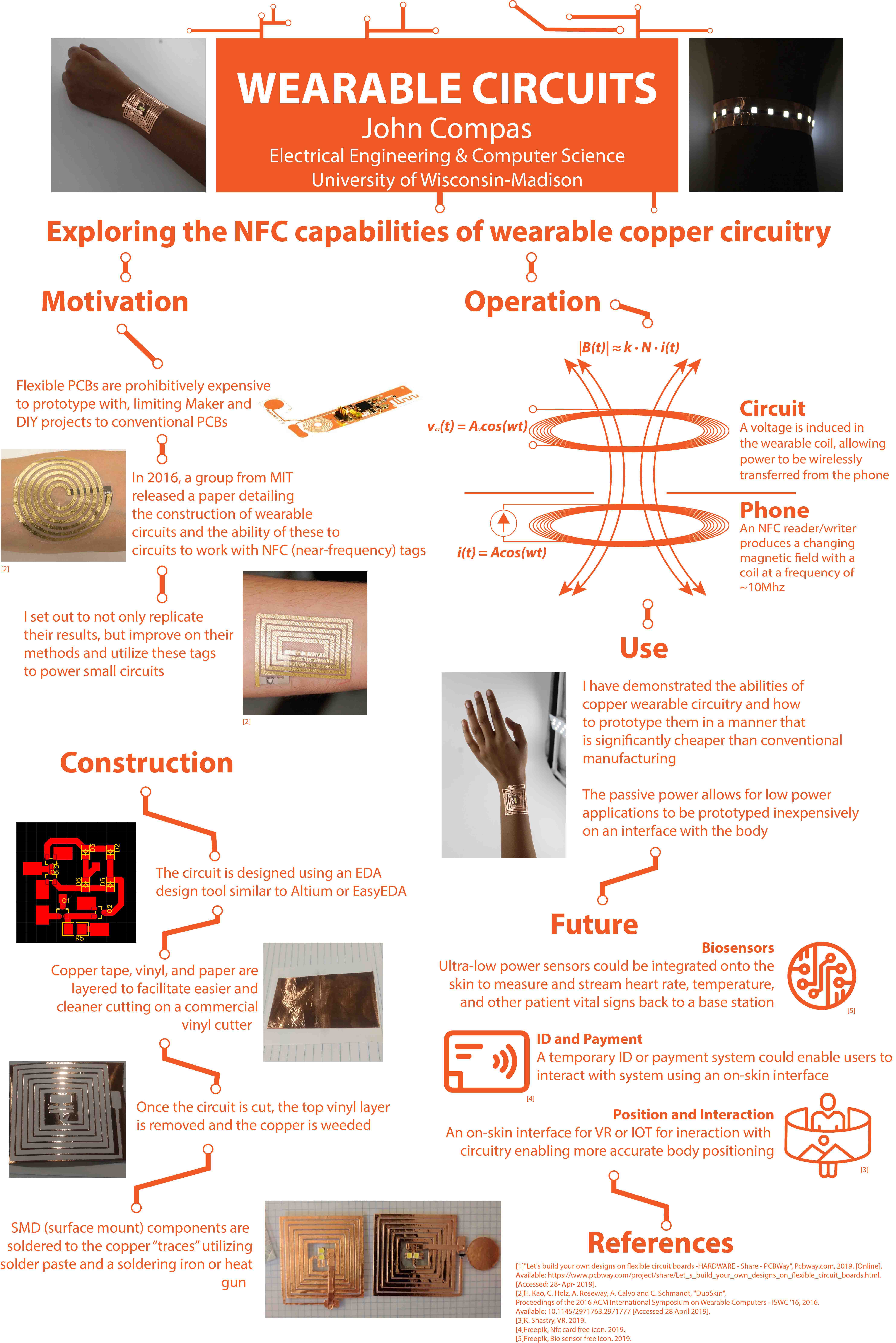
Higher quality PNG: https://drive.google.com/file/d/1DKPj96yx_M83p9iTGX71fJsnb3ftzoNc/view?usp=sharing

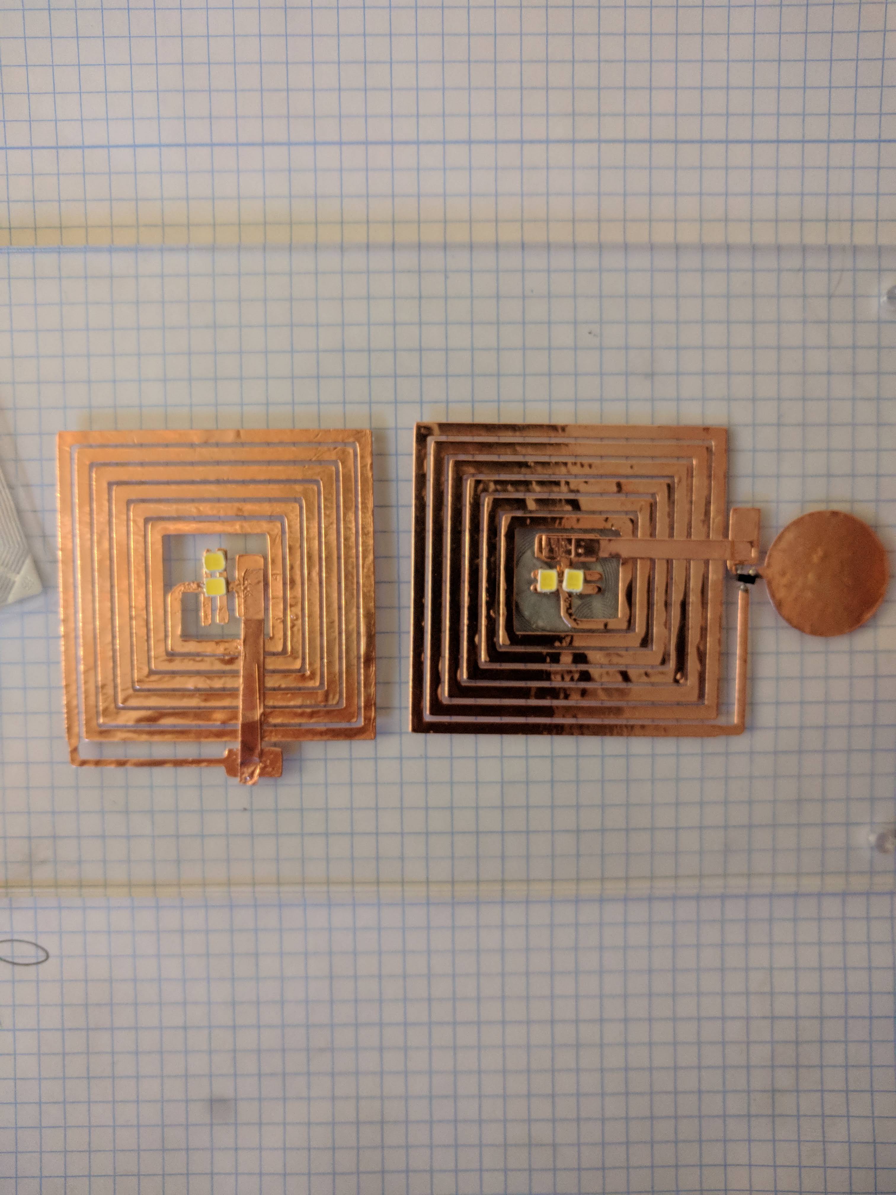
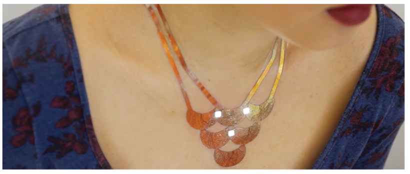
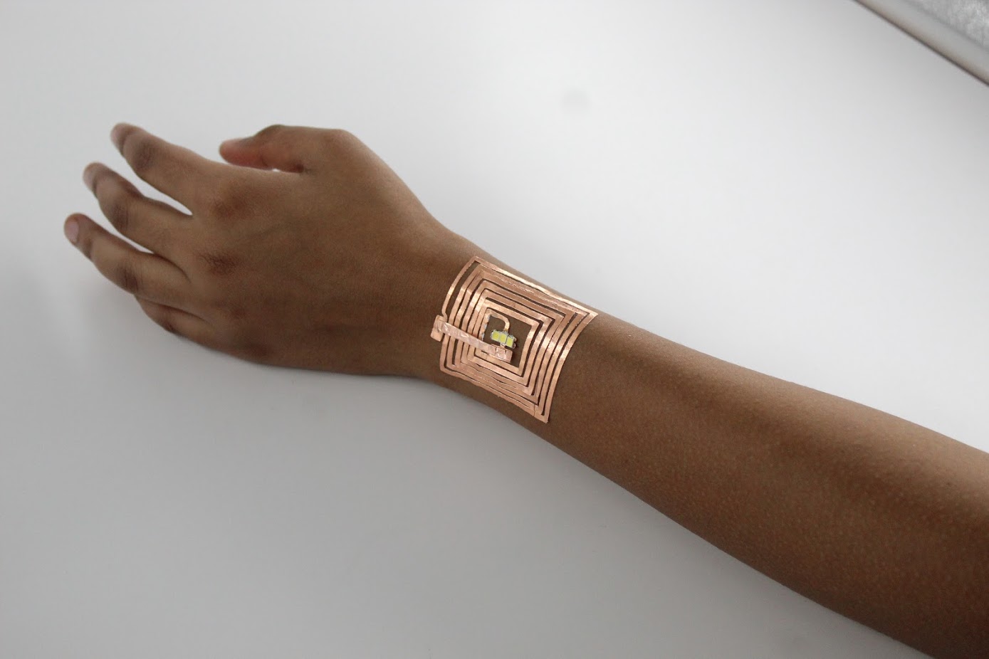
My project is an NFC coil, constructed out of copper foil, that powers devices or LEDs off of a phone or other NFC reader/writer. It is essentially an air-cored transformer, as the coil in the phone creates a magnetic field with alternating intensity. This time-varying magnetic field, due to Faraday’s Law, creates a voltage potential over the coil. This voltage potential can be used to power very-low-power devices such as an LED or (if rectified) microcontrollers.  I stuck to using LEDs for this project because of their ease of use and visual demonstration.

I’m pretty pleased the NFC power works as well as it does, especially with many Android phones that everyone has in their pockets. I would have liked the “powerable” distance to be larger, but per the NFC specifications of <10cm my device performs about as well as commercial ones.

The fact that the LEDs work so well is great. I was guestimating the design of my NFC coil, trying to estimate the inductance I needed. The coil generates ~3.5Vpp when close to a phone and the current produced was on average about 10mA. This gives about 17mW of power. Whether the LEDs would work was up in the air until I tested them.

I accomplished my goal of a remotely powered, wearable circuit. I wasn’t able to get knee deep into the antenna design needed for higher frequency RFID but that would have taken a considerable amount of time and could have been almost impossible.

I didn’t wind up having the time to do any sensor design. I realize that programming my own sensors would have taken a serious amount of time and money. The common RFID / NFC sensors need some sort of devboard or breakout board to be programmable. Figuring out their firmware would have been another massive hurdle.

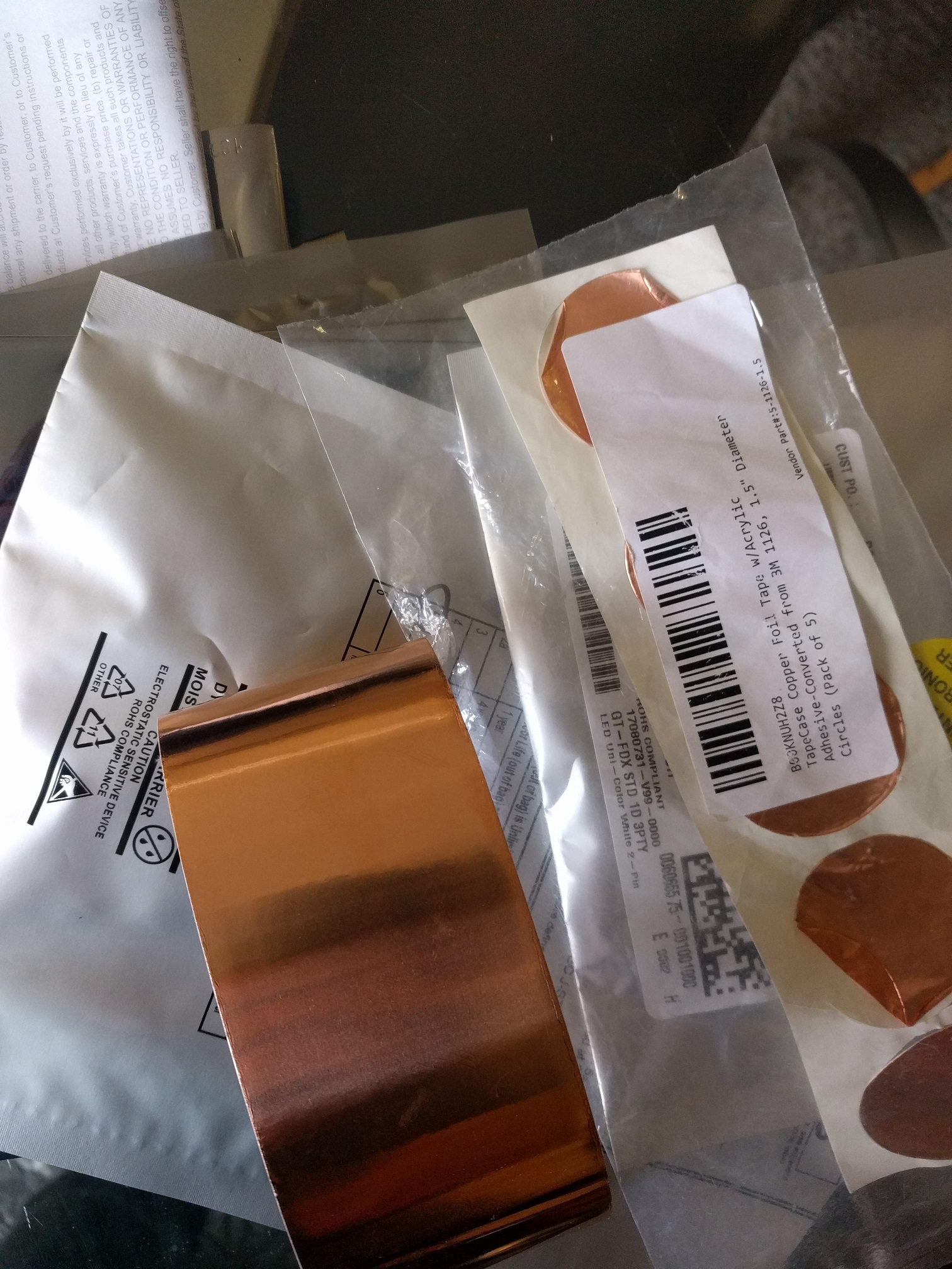
The largest challenge was getting the vinyl cutter to cooperate and not tear up the copper when cutting. It would also sometimes not complete edges or cut quite right.

Through trial and error, I started laminating the copper with a layer of vinyl to protect it. This stopped the cutter from tearing up the surface of the copper. The issues with the cutter not complete edges was a little more persistent. I eventually figured out that small details were (mostly) the cause. Any small corner or other detail in my SVG file could cause the cutter trouble. I took to simplify my SVGs before cutting them.

This mostly solved the issue, but there were still some times when I had to use an Exacto knife to weed part of the circuit.

I would put a lot of effort into getting my hands on some of that Lumilor paint. I potentially would see if I could get the Makerspace or another organization to sponsor purchasing it. I think it could be really interesting in combination with coils that generate induced AC voltage. Finally, I would try to design my own NFC “power” output PCB that would have increased and variable output for testing.

  1. Clear Covering Self-Adhesive
    1. https://www.amazon.com/Magic-Cover-Adhesive-Contact-Projects/dp/B000BPF9QY/ref=sr_1_26?crid=QOW16D2H82TC&keywords=vinyl+adhesive+paper&qid=1551742619&s=gateway&sprefix=vinyl+ad%2Caps%2C195&sr=8-26
    2. Count: 1
    3. Cost: $5.50
  2. Silhouette Temporary Tattoo Paper
    1. https://www.amazon.com/Silhouette-MEDIA-TATTOO-Temporary-Tattoo-Paper/dp/B0043WJ3OA
    2. Count: 1
    3. Cost:  $8.99
  3. Spray Adhesive
    1. https://www.amazon.com/3M-General-Purpose-45-Adhesive/dp/B000PCWRMC
    2. Count: 1
    3. Cost: $5.77
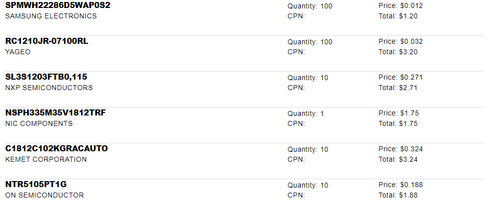
  4. SPMWH22286D5WAP0S2 (Samsung LEDs)
    1. Count: 100
    2. Cost: $1.29
  5. Conductive Guitar Tape
    1. Count: 1
    2. Cost: $5.60
  6. Copper Foil Tape
    1. Count: 1
    2. $4.49

Project Post #7

Wearable Circuits

John Compas

I’ve finished a lot of testing and will work on a few final designs tomorrow, along with getting some good pictures of my designs on somebody.

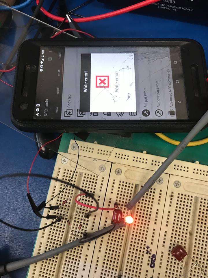
The “antennas” I’ve made power LEDs from a phone’s NFC coil pretty well. However, I have to “trick” the phone into thinking that there is an actual NFC tag near the coil otherwise the phone will not recognize it and will not fully power it.

I’m working on a quick little Android application to try to force the phone to not need to recognize a tag to turn on the NFC read/writer, but that might be more challenging than I thought it would be.

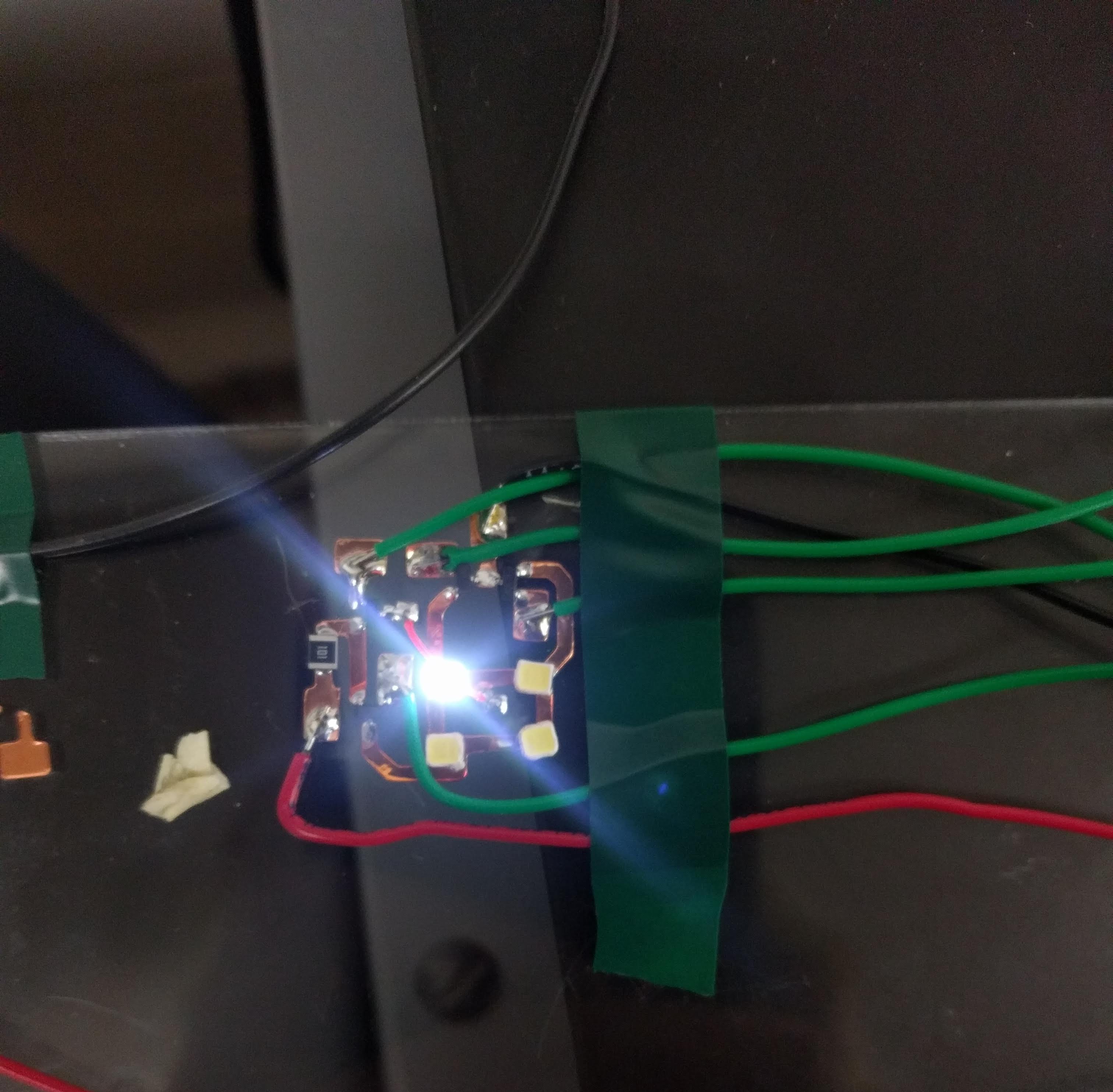
I’ve also finished with a battery-powered version of the circuit, to show that this configuration works with batteries too.

Materials List:

  1. Clear Covering Self-Adhesive 
    1. https://www.amazon.com/Magic-Cover-Adhesive-Contact-Projects/dp/B000BPF9QY/ref=sr_1_26?crid=QOW16D2H82TC&keywords=vinyl+adhesive+paper&qid=1551742619&s=gateway&sprefix=vinyl+ad%2Caps%2C195&sr=8-26
    2. Count: 1
    3. Cost: $5.50
  2. Silhouette Temporary Tattoo Paper
    1. https://www.amazon.com/Silhouette-MEDIA-TATTOO-Temporary-Tattoo-Paper/dp/B0043WJ3OA
    2. Count: 1
    3. Cost:  $8.99
  3. Spray Adhesive
    1. https://www.amazon.com/3M-General-Purpose-45-Adhesive/dp/B000PCWRMC
    2. Count: 1
    3. Cost: $5.77
  4. Speedball Gold Leaf
    1. https://www.amazon.com/Bememo-Imitation-Gilding-Crafting-Decoration/dp/B0722X91YR
    2. Count: 1
    3. Cost: $6.99
  5. SPMWH22286D5WAP0S2 (Samsung LEDs)
    1. Count: 100
  6. RC1210JR-07100RL (100 Ohm Resistor)
    1. Count: 100
  7. SL3S1203FTB0,115 (UHF RFID)
    1. Count: 10
  8. C1812C102KGRACAUTO (Capacitor)
    1. Count: 10
  9. NTR5105PT1G (Diode)
    1. Count: 10
  10.  Conductive Guitar Tape
  11.  NSR201MXT5G (RF Schottky Diode)
  12.  ST25DV16K-IER6T3 (NFC IC)
  13. RF700072 (NFC Antenna)
  14. RF700070 (NFC Antenna)


Project Post #6: Wearable Circuits

Wearable Circuits

John Compas

One – Line Description

Exploring the possibilities of wearable circuitry with and without power sources

Accomplishments

I’ve got NFC power to work with a couple of NFC tags I bought.

They’re easy to integrate into the circuits I’ve built already. I just remove the IC at the feed point of the antenna and attach 30 gauge wires to the feed points. Above, I’ve got a simple full bridge rectifier working although the LEDs light up just as well without one. The rectifier can output about 3 volts DC at 10mA, which isn’t a lot of power, but enough to work with. I’m also going to try to put two of them in parallel to see if I can increase the power output.

The nice thing about the NFC tags is that they are readable from my phone, and many other android phones, so I won’t need a dedicated reader or writer. However, my phone isn’t very powerful and the distance the LED or other circuitry remains power is only a centimeter or two.

I’m going to try to utilize my own NFC antennas, as these frequencies are so low this system is more working like a transformer. Thus, as long as I reasonably match the number of loops of the commercial antennas, this should work decently well. The above design is for 5 leds powered by one tag.

Coming Week

I’ve got a lot to do. I’m going to focus first on getting simple LED circuits to work with these NFC tags and maybe with batteries. I’m mostly thinking of aesthetic wristbands or armbands that have an array of LEDs that wrap around your arm.

I’ve also found that the MOSFETs I bought can seemingly be operated like little “capacitive touch” buttons, although I think they’re actually functioning differently. If I connect the ground of the circuit to the wearer, they can actually turn off the MOFSETs by touching their gates. I’m going to explore using this to turn on and off the LEDs on the wearer and try to get the MOSFETs to hold this state somehow. Ideally, I’d like a pattern to show up on a wearer when they approach an NFC reader.

Materials List:

  1. Clear Covering Self-Adhesive 
    1. https://www.amazon.com/Magic-Cover-Adhesive-Contact-Projects/dp/B000BPF9QY/ref=sr_1_26?crid=QOW16D2H82TC&keywords=vinyl+adhesive+paper&qid=1551742619&s=gateway&sprefix=vinyl+ad%2Caps%2C195&sr=8-26
    2. Count: 1
    3. Cost: $5.50
  2. Silhouette Temporary Tattoo Paper
    1. https://www.amazon.com/Silhouette-MEDIA-TATTOO-Temporary-Tattoo-Paper/dp/B0043WJ3OA
    2. Count: 1
    3. Cost:  $8.99
  3. Spray Adhesive
    1. https://www.amazon.com/3M-General-Purpose-45-Adhesive/dp/B000PCWRMC
    2. Count: 1
    3. Cost: $5.77
  4. Speedball Gold Leaf
    1. https://www.amazon.com/Bememo-Imitation-Gilding-Crafting-Decoration/dp/B0722X91YR
    2. Count: 1
    3. Cost: $6.99
  5. SPMWH22286D5WAP0S2 (Samsung LEDs)
    1. Count: 100
  6. RC1210JR-07100RL (100 Ohm Resistor)
    1. Count: 100
  7. SL3S1203FTB0,115 (UHF RFID)
    1. Count: 10
  8. C1812C102KGRACAUTO (Capacitor)
    1. Count: 10
  9. NTR5105PT1G (Diode)
    1. Count: 10
  10.  Conductive Guitar Tape
  11.  NSR201MXT5G (RF Schottky Diode)
  12.  ST25DV16K-IER6T3 (NFC IC)
  13. RF700072 (NFC Antenna)
  14. RF700070 (NFC Antenna)


Project Post #5: Wearable Circuits

Wearable Circuits

This week, I’ve been looking into rectennas and trying to see if I can power small LEDs from RF from common sources like Wifi routers or leakage from microwaves.

I think doing an incredibly intricate design with impedance matching, ect. might be too much work for the time I have. I’m thinking it will be easier and more practical to experimentally determine what kind of energy I can collect with a small rectifying circuit.

I’ve been inspired by these two examples:

https://ieeexplore-ieee-org.ezproxy.library.wisc.edu/document/8072590

https://ieeexplore-ieee-org.ezproxy.library.wisc.edu/stamp/stamp.jsp?tp=&arnumber=8072590

And this guy (although he’s using a massive antenna): https://www.youtube.com/watch?v=XpLCK88nVgU

I also have ordered new NFC tags, that are much lower frequencies and can be read by your phone.

Materials List:

  1. Clear Covering Self-Adhesive 
    1. https://www.amazon.com/Magic-Cover-Adhesive-Contact-Projects/dp/B000BPF9QY/ref=sr_1_26?crid=QOW16D2H82TC&keywords=vinyl+adhesive+paper&qid=1551742619&s=gateway&sprefix=vinyl+ad%2Caps%2C195&sr=8-26
    2. Count: 1
    3. Cost: $5.50
  2. Silhouette Temporary Tattoo Paper
    1. https://www.amazon.com/Silhouette-MEDIA-TATTOO-Temporary-Tattoo-Paper/dp/B0043WJ3OA
    2. Count: 1
    3. Cost:  $8.99
  3. Spray Adhesive
    1. https://www.amazon.com/3M-General-Purpose-45-Adhesive/dp/B000PCWRMC
    2. Count: 1
    3. Cost: $5.77
  4. Speedball Gold Leaf
    1. https://www.amazon.com/Bememo-Imitation-Gilding-Crafting-Decoration/dp/B0722X91YR
    2. Count: 1
    3. Cost: $6.99
  5. SPMWH22286D5WAP0S2 (Samsung LEDs)
    1. Count: 100
  6. RC1210JR-07100RL (100 Ohm Resistor)
    1. Count: 100
  7. SL3S1203FTB0,115 (UHF RFID)
    1. Count: 10
  8. C1812C102KGRACAUTO (Capacitor)
    1. Count: 10
  9. NTR5105PT1G (Diode)
    1. Count: 10
  10.  Conductive Guitar Tape
  11.  NSR201MXT5G (RF Schottky Diode)
  12.  ST25DV16K-IER6T3 (NFC IC)
  13. RF700072 (NFC Antenna)
  14. RF700070 (NFC Antenna)


Project Post #4

Wearable Circuits

John Compas

Circuit Testing

I successfully soldered my SMD components to the acrylic testbed and found some issues in the process.

  • Soldering the components with an iron is pretty ineffective and doesn’t work well
  • Soldering them with a heat gun works much better, but the adhesive melts easily and the copper starts peeling off of it’s backing
  • The LEDs I bought are incredibly bright, but have a nasty tendency to melt even under low heat
  • The MOSFETs cannot have floating gates, and were finicky even with their gates grounded

The acrylic actually stood up very well to the heat, which I didn’t expect.

Antennas and RFID


I received the UHF-RFID chips, but still don’t have an antenna to test them with.

I found a really cool piece of software called AntSym that, given a set of parameters, will design an antenna for you. As it uses some sort of genetic algorithm, it’s pretty slow but it can optimize the design way better than anything I can do by hand.

Above is one of the designs I’ve been playing around with. I still haven’t quite figured out AntSym, as the gain is lowest in the Z direction as shown by the gain pattern on the left. I’m trying to increase the gain in the Z as much as possible as it is the likely point where the receiver will be.

I’ve been talking to one of my professors about this project, and he has concerns with UHF RFID. At the ~900 Mhz that the chips I’m using are designed to operate at the human skin acts as a relatively good conductor. Thus, it will start reflecting waves away from itself and could create issues. I’m trying to figure out how to model the skin with AntSym, but modeling the dielectric properties of human skin is incredibly complicated. However, he gave me a few commercial UHF RFID tags to test next to skin to see if they work at all.

I also reached out to Alason Sample at UM, to see if his WISP project is still active at all. It’s an open source RFID-powered processing and sensing unit that seems highly applicable for my project.

Directions for Next Week

Circuits:

I think I have a good plan for the issues with soldering the circuits and have developed this process for fabrication:

  1. Layer copper tape in-between vinyl (to prevent tears in the copper layer)
  2. Vinyl cut the circuit
  3. Weed the circuit and fix any issues with the vinyl cutter’s cuts
  4. Transfer the copper layer to a resilient backing, such as acrylic, using transfer paper or another sheet of vinyl
  5. Place and solder components with solder paste and heat gun
  6. Use another sheet of vinyl or transfer paper to pick copper and components off of acrylic
  7. Spray the back of the copper layer and vinyl with adhesive
  8. Adhere circuit with vinyl top layer onto tattoo paper
  9. Done! Try it on a person

This method will result in a circuit layered on both sides with a non-conductive layer.

As for actual circuit designs, I’m very interested in trying to have these units be batteryless. At first, I was mainly thinking of passive power through RFID frequencies or simple induction.

However, I think something like a small solar cell would be interesting to experiment with and could potentially be more useful. I’m going to look into what I could power off of a small solar cell, and then base my design off of these power requirements.

Antennas:

It seems like it would be very easy to get lost trying to perfectly model the skin while designing the “perfect” antenna. So I will focus on creating an antenna from a standard design and seeing how well it works, if at all. In their DuoSkin paper, MIT didn’t seem to focus much on the antenna design at all, so I think the antenna will probably work although not well.


Materials List:

  1. Clear Covering Self-Adhesive 
    1. https://www.amazon.com/Magic-Cover-Adhesive-Contact-Projects/dp/B000BPF9QY/ref=sr_1_26?crid=QOW16D2H82TC&keywords=vinyl+adhesive+paper&qid=1551742619&s=gateway&sprefix=vinyl+ad%2Caps%2C195&sr=8-26
    2. Count: 1
    3. Cost: $5.50
  2. Silhouette Temporary Tattoo Paper
    1. https://www.amazon.com/Silhouette-MEDIA-TATTOO-Temporary-Tattoo-Paper/dp/B0043WJ3OA
    2. Count: 1
    3. Cost:  $8.99
  3. Spray Adhesive
    1. https://www.amazon.com/3M-General-Purpose-45-Adhesive/dp/B000PCWRMC
    2. Count: 1
    3. Cost: $5.77
  4. Speedball Gold Leaf
    1. https://www.amazon.com/Bememo-Imitation-Gilding-Crafting-Decoration/dp/B0722X91YR
    2. Count: 1
    3. Cost: $6.99
  5. SPMWH22286D5WAP0S2 (Samsung LEDs)
    1. Count: 100
  6. RC1210JR-07100RL (100 Ohm Resistor)
    1. Count: 100
  7. SL3S1203FTB0,115 (UHF RFID)
    1. Count: 10
  8. C1812C102KGRACAUTO (Capacitor)
    1. Count: 10
  9. NTR5105PT1G (Diode)
    1. Count: 10
  10.  Conductive Guitar Tape


Project Post #3: Circuit Tattoo

Circuit Tattoo

John Compas

I have ordered thicker conductive material, mostly conductive tape. I’ll test it on the vinyl cutter tomorrow morning to see how well it performs.

I’ve ordered some SMD components from Arrow to test out my first few designs, such as a multiplexed 2×2 array.

The design will utilize the SMD components to create an array that can be driven by the circuit playground.

I’m researching the antennas for the UHF RFID ICs that I ordered and will use AntSym to design them. I’m currently getting started working with it to determine how well it will work for me.

I think the antennas will certainly be the most challenging aspect of this project, along with getting the conductive material for the tattoos right. However, I think this new round of material will work much better than the leaf.

Project Post #2: Tattoo Circuits

Tattoo Circuits

John Compas

Weekly Accomplishments

I have already ordered, and received all the materials needed for first prototypes:

  1. Clear Covering Self-Adhesive 
    1. https://www.amazon.com/Magic-Cover-Adhesive-Contact-Projects/dp/B000BPF9QY/ref=sr_1_26?crid=QOW16D2H82TC&keywords=vinyl+adhesive+paper&qid=1551742619&s=gateway&sprefix=vinyl+ad%2Caps%2C195&sr=8-26
    2. Count: 1
    3. Cost: $5.50
  2. Silhouette Temporary Tattoo Paper
    1. https://www.amazon.com/Silhouette-MEDIA-TATTOO-Temporary-Tattoo-Paper/dp/B0043WJ3OA
    2. Count: 1
    3. Cost:  $8.99
  3. Spray Adhesive
    1. https://www.amazon.com/3M-General-Purpose-45-Adhesive/dp/B000PCWRMC
    2. Count: 1
    3. Cost: $5.77
  4. Speedball Gold Leaf
    1. https://www.amazon.com/Bememo-Imitation-Gilding-Crafting-Decoration/dp/B0722X91YR
    2. Count: 1
    3. Cost: $6.99

I have most of the electrical components I want to test and solder onto the first prototypes.

I also designed and laser cut a testbed on acrylic, to simplify the layout and testing process before I try it on skin.

I haven’t changed too much in my approach yet, but I need to do more testing of the actual vinyl cutter.


Temporary Circuitry Tattoo: Project Post #1

Temporary Circuitry Tattoo

John Compas


I would like to explore the possibilities of using gold leaf, tattoo paper, and SMT components to create wearable circuits. These temporary tattoos could be artistic, lighting up in response to the wearer’s environment, or more utilitarian, such as utilizing near RFID to respond to a request with sensor data and an ID. I’m interested in investigating the space of what is possible with this topology especially with antennas and RFID technology.

My project is for anyone, to show to demonstrate the capabilities of the technology and fascinate people.

Interfacing with a complete device would be simple. The tattoo would be applied like any other with a spray bottle of water to get the adhesive to activate on the wearer’s skin. In the case a passive UHF RFID tag, the sensor would lay dormant until activated by a strong RF emitter. Storing the received RF energy in a capacitor, the integrated sensor IC would read a sensor value and respond to the request as dictated by UHF protocol ISO 18000-6C. The reader would then report this value to a tablet or phone.

More artistic designs could change LED color and intensity based on skin temperature and conductivity, or by the intensity of received RF signals in a certain band. For example, LEDs could visualize the intensity of different frequency signals around the wearer using multiple antennas with varying resonant frequencies.

Existing work as focused more on either ease of use, or improving some technical aspect of this technology.  I would like to focus on antennas and poetic interaction with the user.

Project Inspiration

Duo-Skin, MIT

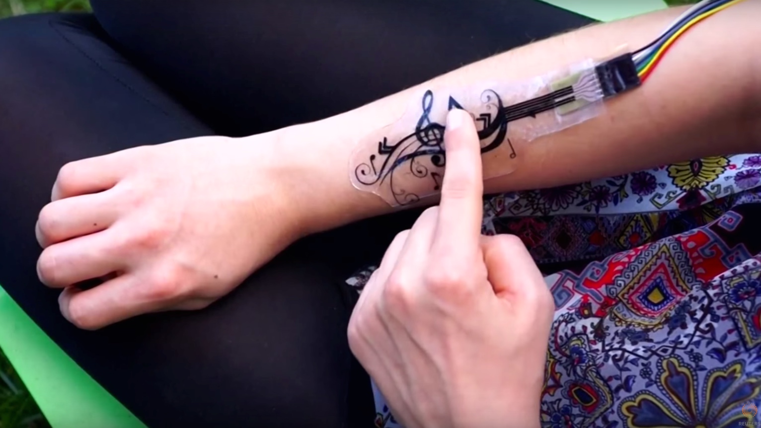
A project from a group of MIT, Duo-Skin aimed to demonstrate the ease of creating wearable, temporary tattoos. They were successful in creating computer-powered MIDI controllers, RFID tags, and letting a team of volunteers quickly create their own circuitry.


iSkin, Carnegie Mellon

iSkin was a much more engineered approach and came before the MIT study. They demonstrated interfaces using layers of cPDMS (a silicone elastomer) and touch. The study is good source of detailed information about how their capacitive touch sensors work but was less “friendly” than the Duo-Skin.

Project Sketch

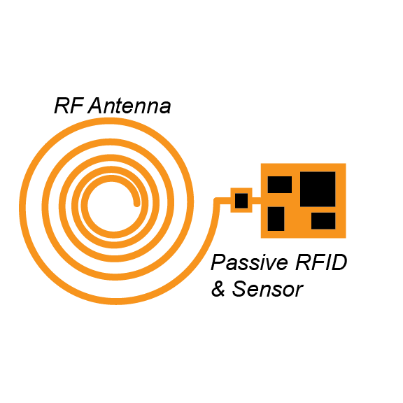
Example UHF RFID Sensor, passively powered that responds with ID and data.

(I’m not great at antenna design, the feedpoint should probably be in the middle, but this is the idea)

Materials & Tools

  • Gold leaf
  • Tattoo paper
  • SMT capacitors, transistors, LEDs, and ICs
  • Altium Designer
  • Small lithium-ion coin cell batteries
  • Impedance analyzer
  • Oscilloscope
  • DC power supply
  • Solder paste or solder
  • Solder gun, heat gun, and reflow oven
  • Laser cutter (potential)
  • Electric stencil cutter

Skills & Concepts

I will need to research antenna design thoroughly, as I have little experience with it in the past. I’m aware of the challenges with circuitry and antennas in the gigahertz range but have never designed any myself.

Cutting the stencils will (hopefully) not be done by hand, but the layering of the tattoos will need to be done by me. Soldering the SMT components to the gold leaf will also potentially be a challenge. Burning the leaf out might be easy, but it seems like a challenge that has been overcome in the past so I’m hopeful that I will find a method.

Timeline

March 8: Order Prototype Materials, Find Tools & Initial Design

  • Generate a more detailed list of materials needed for an initial prototype and find suppliers online
  • Order materials and components
  • Layout initial circuit designs in EasyEDA, layout footprints in Altium and generate stencil cut-outs

March 13: Demo of Circuitry

  • Utilize gold leaf on cardboard or another surface to create initial powered circuitry
  • Attempt to transfer to body, and develop a procedure for insulating layers

March 25: Duplication

  • Successfully duplicate previous work, with battery-powered sensors, capacitive touch buttons, and LEDs
  • Attempt to create RFID responsive tags with a simple IC and antenna
  • Analyze antenna properties, characteristic impedance,  and model gold leaf in antenna design software such as EMWORKS

April 8: Improvement

  • Start work on passively powered RFID tags & sensor
  • Iterate on the circuit construction process
  • If work is progressing well, attempt a powered Bluetooth LE circuit

April 22: Environmental Testing

  • Demonstrate design in the real world, and test durability and usability
  • Make small changes based on the user experience of wearers
  • Prepare multiple samples and demonstration “tattoos” for the show in April.

Fallback

As a whole, I see the antenna aspects of this project as the most challenging. I have a decent amount of experience in conventional circuit design and microcontroller programming. The circuits here are not particularly challenging, outside of the feed point with the antenna.

The gold leaf could present a challenge, but DuoSkin reported it as relatively durable with sufficient trace widths. If it isn’t working for some reason, other conductive tape or material could be attempted.

As a bare minimum, I expect to at least duplicate the results gathered by MIT in their DuoSkin study. Part of the aim of that paper was the technical ease at which circuits like these could be created, so I don’t anticipate duplication taking longer than the two months that we have.